MT9D131C12STC Aptina LLC, MT9D131C12STC Datasheet - Page 13
MT9D131C12STC
Manufacturer Part Number
MT9D131C12STC
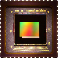
Description
SENSOR IMAGE 2MP CMOS 48-CLCC
Manufacturer
Aptina LLC
Type
CMOS Imagingr
Specifications of MT9D131C12STC
Pixel Size
2.8µm x 2.8µm
Active Pixel Array
1600H x 1200V
Frames Per Second
15
Voltage - Supply
2.5 V ~ 3.1 V
Package / Case
48-CLCC
Sensor Image Color Type
Color
Sensor Image Size
1600x1200Pixels
Operating Supply Voltage (min)
1.7/2.5V
Operating Supply Voltage (typ)
1.8/2.8V
Operating Supply Voltage (max)
1.95/3.1V
Operating Temp Range
-30C to 70C
Package Type
CLCC
Operating Temperature Classification
Commercial
Mounting
Surface Mount
Pin Count
48
Lead Free Status / RoHS Status
Lead free / RoHS Compliant
For Use With
557-1253 - KIT HEAD BOARD FOR MT9D131557-1248 - KIT DEV FOR MT9D131
Lead Free Status / RoHS Status
Compliant, Lead free / RoHS Compliant
Other names
557-1311
Available stocks
Company
Part Number
Manufacturer
Quantity
Price
Company:

Part Number:
MT9D131C12STC
Manufacturer:
VIKING
Quantity:
120 000
Part Number:
MT9D131C12STC
Manufacturer:
APTINA
Quantity:
20 000
Company:
Part Number:
MT9D131C12STCH ES
Manufacturer:
Aptina LLC
Quantity:
135


Figure 6:
Die Outline
Figure 7:
PDF: 09005aef824c90ce/Source: 09005aef824c90d6
MT9D131_LDS_2.fm - Rev. B 3/07 EN
Sensor Core Block Diagram
Optical Center Offset
Note:
The core of the sensor is an active-pixel array. The timing and control circuitry
sequences through the rows of the array, resetting and then reading each row. In the
time interval between resetting a row and reading that row, the pixels in that row inte-
grate incident light. The exposure is controlled by varying the time interval between
reset and readout. After a row is read, the data from the columns is sequenced through
an analog signal chain (providing offset correction and gain), and then through an ADC.
The output from the ADC is a 10-bit value for each pixel in the array. The pixel array con-
tains optically active and light-shielded “black” pixels. The black pixels are used to pro-
vide data for on-chip offset correction algorithms (black level control).
Active-Pixel Sensor
Figure not to scale.
1600H x 1200V
Analog Processing
(APS) Array
UXGA
Last Clear Pixel
(Col 1683, Row 1235)
MT9D131: 1/3.2-Inch 2-Mp SOC Digital Image Sensor
(167.84μm, 2.06μm)
Optical Center
8199.35μm
(bare die)
(0μm, 0μm)
Die Center
13
Timing and Control
Control Register
ADC
First Clear Pixel
(Col 52, Row 20)
Micron Technology, Inc., reserves the right to change products or specifications without notice.
PLL
Signals
Serial
Data
Sync
Architecture Overview
Out
I/O
©2006 Micron Technology, Inc. All rights reserved.
Preliminary
Related parts for MT9D131C12STC
Image
Part Number
Description
Manufacturer
Datasheet
Request
R

Part Number:
Description:
SENSOR IMAGE VGA COLOR CMOS PLCC
Manufacturer:
Aptina LLC
Datasheet:

Part Number:
Description:
IC SENSOR IMAGE COLOR 48CLCC
Manufacturer:
Aptina LLC
Datasheet:

Part Number:
Description:
SENSOR IMAGE 1.3MP CMOS 48-CLCC
Manufacturer:
Aptina LLC
Datasheet:

Part Number:
Description:
SENSOR IMAGE VGA MONO 52IBGA
Manufacturer:
Aptina LLC
Datasheet:

Part Number:
Description:
SENSOR IMAGE VGA COLOR 48CLCC
Manufacturer:
Aptina LLC
Datasheet:

Part Number:
Description:
SENSOR IMAGE COLOR CMOS 48-PLCC
Manufacturer:
Aptina LLC
Datasheet:

Part Number:
Description:
KIT HEAD BOARD FOR MT9P031
Manufacturer:
Aptina LLC
Datasheet:

Part Number:
Description:
KIT HEAD BOARD FOR MT9D131
Manufacturer:
Aptina LLC
Datasheet:

Part Number:
Description:
KIT HEAD BOARD FOR MT9P031
Manufacturer:
Aptina LLC
Datasheet:

Part Number:
Description:
KIT HEAD BOARD FOR MT9M032
Manufacturer:
Aptina LLC
Datasheet:

Part Number:
Description:
PARALLEL HEADBOARD FOR MT9M032
Manufacturer:
Aptina LLC
Datasheet:
Part Number:
Description:
SENSOR IMAGE VGA COLOR CMOS PLCC
Manufacturer:
Aptina LLC
Datasheet:
Part Number:
Description:
IC SENSOR IMAGE COLOR 48CLCC
Manufacturer:
Aptina LLC
Datasheet:
