MT9D131C12STC Aptina LLC, MT9D131C12STC Datasheet - Page 4
MT9D131C12STC
Manufacturer Part Number
MT9D131C12STC
Description
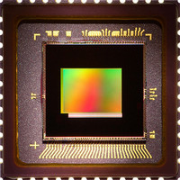
SENSOR IMAGE 2MP CMOS 48-CLCC
Manufacturer
Aptina LLC
Type
CMOS Imagingr
Specifications of MT9D131C12STC
Pixel Size
2.8µm x 2.8µm
Active Pixel Array
1600H x 1200V
Frames Per Second
15
Voltage - Supply
2.5 V ~ 3.1 V
Package / Case
48-CLCC
Sensor Image Color Type
Color
Sensor Image Size
1600x1200Pixels
Operating Supply Voltage (min)
1.7/2.5V
Operating Supply Voltage (typ)
1.8/2.8V
Operating Supply Voltage (max)
1.95/3.1V
Operating Temp Range
-30C to 70C
Package Type
CLCC
Operating Temperature Classification
Commercial
Mounting
Surface Mount
Pin Count
48
Lead Free Status / RoHS Status
Lead free / RoHS Compliant
For Use With
557-1253 - KIT HEAD BOARD FOR MT9D131557-1248 - KIT DEV FOR MT9D131
Lead Free Status / RoHS Status
Compliant, Lead free / RoHS Compliant
Other names
557-1311
Available stocks
Company
Part Number
Manufacturer
Quantity
Price
Company:

Part Number:
MT9D131C12STC
Manufacturer:
VIKING
Quantity:
120 000
Part Number:
MT9D131C12STC
Manufacturer:
APTINA
Quantity:
20 000
Company:
Part Number:
MT9D131C12STCH ES
Manufacturer:
Aptina LLC
Quantity:
135


Signal Description
Table 3:
PDF: 09005aef824c90ce/Source: 09005aef824c90d6
MT9D131_LDS_2.fm - Rev. B 3/07 EN
FRAME_VALID
LINE_VALID
STANDBY
D
EXTCLK
VAAPIX
V
RESET#
PIXCLK
Name
OUT
S
S
V
A
D
TEST
SCLK
DD
V
V
ADDR
DATA
DD
GND
GND
DD
AA
[7:0]
PLL
Q
Signal Description
8, 9, 10, 11, 14, 15, 16,
4, 6, 7, 13, 18, 19, 23,
2, 3, 12, 24, 25, 36
28, 37, 42, 43, 45
21, 22, 44, 5
CLCC Pin
29, 30, 31
32, 33
26, 27
40
39
38
20
34
35
17
48
47
46
41
1
Supply
Supply
Supply
Supply
Supply
Supply
Supply
Input
Input
Input
Input
Input
Input
Input
Input
Input
Input
Type
I/O
MT9D131: 1/3.2-Inch 2-Mp SOC Digital Image Sensor
Master clock signal (can either drive the on-chip PLL or bypass it).
Master reset signal, active LOW.
Controls sensor’s standby mode.
Reserved for factory test. Tie to digital ground during normal
operation.
Two-wire serial interface clock.
Selects device address for the two-wire serial interface. The
address is 0x90 when S
also R0x0D:0[10].
Eight-bit image data output or most significant bits (MSB) of 10-
bit sensor bypass mode.
Identifies rows in the active image.
Identifies lines in the active image.
Pixel clock. To be used for sampling D
LINE_VALID.
Two-wire serial interface data.
Digital power (1.8V).
PLL power (2.8V).
Analog power (2.8V).
Pixel array power (2.8V).
I/O power (nominal 1.8V or 2.8V).
Analog ground.
Digital, I/O, and PLL ground.
4
Micron Technology, Inc., reserves the right to change products or specifications without notice.
ADDR
Description
is tied LOW, 0xBA if tied HIGH. See
©2006 Micron Technology, Inc. All rights reserved.
OUT
Signal Description
, FRAME_VALID, and
Preliminary
Related parts for MT9D131C12STC
Image
Part Number
Description
Manufacturer
Datasheet
Request
R

Part Number:
Description:
SENSOR IMAGE VGA COLOR CMOS PLCC
Manufacturer:
Aptina LLC
Datasheet:

Part Number:
Description:
IC SENSOR IMAGE COLOR 48CLCC
Manufacturer:
Aptina LLC
Datasheet:

Part Number:
Description:
SENSOR IMAGE 1.3MP CMOS 48-CLCC
Manufacturer:
Aptina LLC
Datasheet:

Part Number:
Description:
SENSOR IMAGE VGA MONO 52IBGA
Manufacturer:
Aptina LLC
Datasheet:

Part Number:
Description:
SENSOR IMAGE VGA COLOR 48CLCC
Manufacturer:
Aptina LLC
Datasheet:

Part Number:
Description:
SENSOR IMAGE COLOR CMOS 48-PLCC
Manufacturer:
Aptina LLC
Datasheet:

Part Number:
Description:
KIT HEAD BOARD FOR MT9P031
Manufacturer:
Aptina LLC
Datasheet:

Part Number:
Description:
KIT HEAD BOARD FOR MT9D131
Manufacturer:
Aptina LLC
Datasheet:

Part Number:
Description:
KIT HEAD BOARD FOR MT9P031
Manufacturer:
Aptina LLC
Datasheet:

Part Number:
Description:
KIT HEAD BOARD FOR MT9M032
Manufacturer:
Aptina LLC
Datasheet:

Part Number:
Description:
PARALLEL HEADBOARD FOR MT9M032
Manufacturer:
Aptina LLC
Datasheet:
Part Number:
Description:
SENSOR IMAGE VGA COLOR CMOS PLCC
Manufacturer:
Aptina LLC
Datasheet:
Part Number:
Description:
IC SENSOR IMAGE COLOR 48CLCC
Manufacturer:
Aptina LLC
Datasheet:
