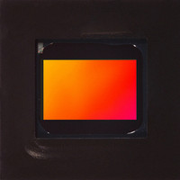
MT9V022IA7ATM Aptina LLC, MT9V022IA7ATM Datasheet - Page 3

MT9V022IA7ATM
Manufacturer Part Number
MT9V022IA7ATM
Description
SENSOR IMAGE VGA MONO 52IBGA
Manufacturer
Aptina LLC
Type
CMOS Imagingr
Series
DigitalClarity®r
Specifications of MT9V022IA7ATM
Pixel Size
6µm x 6µm
Active Pixel Array
752H x 480V
Frames Per Second
60
Voltage - Supply
3.3V
Package / Case
52-IBGA
Sensor Image Color Type
Monochrome
Sensor Image Size Range
250,920 to 480,000Pixels
Sensor Image Size
752x480Pixels
Operating Supply Voltage (min)
3V
Operating Supply Voltage (typ)
3.3V
Operating Supply Voltage (max)
3.6V
Operating Temp Range
-40C to 85C
Package Type
IBGA
Operating Temperature Classification
Industrial
Mounting
Surface Mount
Pin Count
52
Lead Free Status / RoHS Status
Lead free / RoHS Compliant
Other names
557-1205
Available stocks
Company
Part Number
Manufacturer
Quantity
Price
LVDS Serial Output (Stand-Alone and Stereoscopic Operation)
Figure 2:
Pixel Data Format and Pixel Array Structure
PDF:09005aef8201ffc3/Source: 09005aef81ff2525
MT9V022_Product_Brief - Rev. A 1/06 EN
BYPASS_CLKIN
SER_DATAIN
LVDS
LVDS
1. PLL in non-bypass mode
2. PLL in x 18 mode (stereoscopy)
X 1 8/X 1 2 PL L
LVDS Stereoscopic Topology
SENSOR
SENSOR
SLAVE
SER_DATAOUT
In slave mode, the sensor accepts both external integration and readout controls.
The integration time is programmed through the two-wire serial interface during master
or snapshot modes, or controlled via an externally generated control signal during slave
mode.
The LVDS interface allows for the streaming of sensor data serially to a standard off-the
shelf deserializer up to 8 meters away from the sensor. The LVDS serial output could
either be data from a single sensor (stand-alone) or stream-merged data from a pair
(master and slave) of synchronized MT9V022 devices.
The pixels (and controls) are packeted—12-bit packets for stand-alone mode and 18-bit
packets (2 frame bits and 8 data bits from each sensor) for stereoscopic mode. All serial
signals (clock and data) is LVDS.
An LVDS connection overview for a single MT9V022 and for stereoscopic pair of
MT9V022 devices is shown in Figure 2.
The MT9V022 pixel array is configured of 782 columns by 492 rows, as shown in Figure 3.
The left 26 columns and the top 8 rows of pixels are optically black and can be used to
monitor the black level. The black row data is used internally for the automatic black
level adjustment.
LVDS
SHIFT_CLKOUT
LVDS
BYPASS_CLKIN
SER_DATAIN
LVDS
LVDS
1. PLL in bypass mode
MT9V022: 1/3-Inch Wide-VGA Digital Image Sensor
3
Pixel Data Format and Pixel Array Structure
SENSOR
LV and FV are embedded in the data stream
MASTER
SER_DATAOUT
SLAVE
FROM
PIXEL
8
Micron Technology, Inc., reserves the right to change products or specifications without notice.
LVDS
DS92LV16
LVDS
SHIFT_CLKOUT
MASTER
PIXEL
FROM
8
26.6 MHz
26.6 MHz
Osc.
Osc.
©2006 Micron Technology, Inc. All rights reserved.
5m (maximum)


