MT9M413C36STM Aptina LLC, MT9M413C36STM Datasheet - Page 15
MT9M413C36STM
Manufacturer Part Number
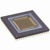
MT9M413C36STM
Description
SENSOR IMAGE MONO CMOS 280-PGA
Manufacturer
Aptina LLC
Type
CMOS Imagingr
Specifications of MT9M413C36STM
Pixel Size
12µm x 12µm
Active Pixel Array
1280H x 1024V
Frames Per Second
500
Voltage - Supply
3.3V
Package / Case
280-PGA
Sensor Image Color Type
Monochrome
Sensor Image Size
1280x1024Pixels
Operating Supply Voltage (min)
3V
Operating Supply Voltage (max)
3.6V
Operating Temp Range
-5C to 60C
Package Type
CPGA
Operating Temperature Classification
Commercial
Mounting
Through Hole
Pin Count
280
Lead Free Status / RoHS Status
Contains lead / RoHS non-compliant
Other names
557-1153


Table 3:
09005aef806807ca
MT9M413C36STC.fm - Ver. 3.0 1/04 EN
PIN NUMBER(S)
G16, E10, C13, B4,
B8, C7, F4, M2,
B14,
F15, R13, T12, B1,
H4, N4, R3, T5, U5,
W7, U9, U11, T16,
B16
G5, D4, G4, K3,
N5, P5, U4, T7,
T10, U7, U13 K5,
B15, B17, H17,
D12, D11, E17, C9,
D8 M4, T11,U18,
B5,U15
R18, P18, K18,J18
T17, N16, L17,
K17, J15, R17
L15
M18
N17
K16, M15
P17
M16
K15
Pin Description (Continued)
SIGNAL NAME
VDD_IO
DGND_IO
VAA
AGND
VLN1
VLN2
VLP
VREF1
VREF2
VREF3
VCLAMP3
FUNCTION
Power supply for digital pad ring.
Digital ground for pad ring.
Power supply for analog processing circuitry (column buffers, ADC,
and support).
Ground for analog signal processing circuitry.
Bias setting for pixel source follower operating current. Impedance:
3kΩ, 10pF. Decoupling capacitors recommended.
The bias setting for the ADC is generated on-chip. A decoupling
capacitor to ground is recommended. External biasing may be
preferable to optimize performance. Impedance: 3kΩ, 10pF.
Bias setting voltage for the column source follower operating
current. Impedance: 3kΩ, 10pF. Decoupling capacitor recommended.
ADC reference input voltage that sets the maximum input signal
level (defines the level where the FF code occurs) and thus sets the
size of the least significant bit (LSB) in the analog to digital
conversion process. A smaller VREF1 produces a smaller LSB, which
means a smaller analog signal level input is required to produce the
same digital code out. Likewise, a larger VREF1 produces a larger
LSB, which means a larger analog signal level input is required to
produce the same digital code out. Thus the reference value can be
used like a global gain adjustment (halving this voltage doubles the
gain). This signal has two pin connections to minimize internal
losses during high-speed operation. User voltage source must supply
a transient current of 100mA at a frequency of 500 kHz with a 2%
duty cycle. Decoupling capacitors to AGND of ~1µF (ceramic) and
100µF (electrolytic) placed as close to the package pins as possible
are usually sufficient to filter out this required current transient.
ADC reference used for the calibration operation. User voltage
source must supply a transient current of 20mA at a frequency of
500 kHz with a 2% duty cycle. A ceramic decoupling capacitor to
AGND of ~0.1µF is usually sufficient to filter out this required
current transient.
Dark offset cancellation positive input reference, tied to the
pedestal voltage to be added to the signal.
Dark offset cancellation negative input reference. User voltage
source must supply a transient current of 40mA at a frequency of
500 kHz with a 2% duty cycle. A ceramic decoupling capacitor to
AGND of ~0.1µF to 1µF is usually sufficient to filter out this required
current transient.
1.3-MEGAPIXEL CMOS ACTIVE-PIXEL
15
Micron Technology, Inc., reserves the right to change products or specifications without notice.
DIGITAL IMAGE SENSOR
©2004 Micron Technology, Inc. All rights reserved.
Related parts for MT9M413C36STM
Image
Part Number
Description
Manufacturer
Datasheet
Request
R

Part Number:
Description:
SENSOR IMAGE VGA COLOR CMOS PLCC
Manufacturer:
Aptina LLC
Datasheet:

Part Number:
Description:
IC SENSOR IMAGE COLOR 48CLCC
Manufacturer:
Aptina LLC
Datasheet:

Part Number:
Description:
SENSOR IMAGE 1.3MP CMOS 48-CLCC
Manufacturer:
Aptina LLC
Datasheet:

Part Number:
Description:
SENSOR IMAGE 2MP CMOS 48-CLCC
Manufacturer:
Aptina LLC
Datasheet:

Part Number:
Description:
SENSOR IMAGE VGA MONO 52IBGA
Manufacturer:
Aptina LLC
Datasheet:

Part Number:
Description:
SENSOR IMAGE VGA COLOR 48CLCC
Manufacturer:
Aptina LLC
Datasheet:

Part Number:
Description:
SENSOR IMAGE COLOR CMOS 48-PLCC
Manufacturer:
Aptina LLC
Datasheet:

Part Number:
Description:
KIT HEAD BOARD FOR MT9P031
Manufacturer:
Aptina LLC
Datasheet:

Part Number:
Description:
KIT HEAD BOARD FOR MT9D131
Manufacturer:
Aptina LLC
Datasheet:

Part Number:
Description:
KIT HEAD BOARD FOR MT9P031
Manufacturer:
Aptina LLC
Datasheet:
Part Number:
Description:
SENSOR IMAGE VGA COLOR CMOS PLCC
Manufacturer:
Aptina LLC
Datasheet:
Part Number:
Description:
IC SENSOR IMAGE COLOR 48CLCC
Manufacturer:
Aptina LLC
Datasheet:
Part Number:
Description:
SENSOR IMAGE 2MP CMOS 48-CLCC
Manufacturer:
Aptina LLC
Datasheet:
