MT9M413C36STM Aptina LLC, MT9M413C36STM Datasheet - Page 24
MT9M413C36STM
Manufacturer Part Number
MT9M413C36STM
Description
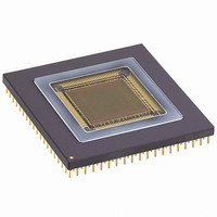
SENSOR IMAGE MONO CMOS 280-PGA
Manufacturer
Aptina LLC
Type
CMOS Imagingr
Specifications of MT9M413C36STM
Pixel Size
12µm x 12µm
Active Pixel Array
1280H x 1024V
Frames Per Second
500
Voltage - Supply
3.3V
Package / Case
280-PGA
Sensor Image Color Type
Monochrome
Sensor Image Size
1280x1024Pixels
Operating Supply Voltage (min)
3V
Operating Supply Voltage (max)
3.6V
Operating Temp Range
-5C to 60C
Package Type
CPGA
Operating Temperature Classification
Commercial
Mounting
Through Hole
Pin Count
280
Lead Free Status / RoHS Status
Contains lead / RoHS non-compliant
Other names
557-1153


Lens Selection
explained in detail at http://www.micron.com/prod-
ucts/imaging/technology/index.html on our web site.
The following information applies specifically to the
MI-MV13 megapixel image sensor.
Format
fits most closely, but not exactly, within the optical for-
mat corresponding to the 1-inch specification. Some
1-inch optical format lenses have been shown to work
well with this sensor. Typical 1-inch lens examples are
Computer V2513, V5013, and V7514. F-mount lenses
provide another possible lens solution due to their
large image circle.
Mounting
the threading of the lens' barrel as well as the distance
the back flange of the lens should be from the image
sensor for the lens to properly form an image. Typical
lens mounting standards for the MI-MV13 are:
Table 11: Lens Mounting Standards
C-to F-mount adapter for greater lens flexibility.
Field of View and Focal Length
on both the focal length of the imaging lens and the
width of the image sensor. As most of the image infor-
mation humans pay attention to generally falls within
a 45-degree horizontal field of view, many camera sys-
tems attempt to imitate this field of view. However, in
some cases a telephoto system (with a narrow field of
view, say less than 20 degrees), or a wide angle system
(with a wide field of view, say more than 60 degrees)
09005aef806807ca
MT9M413C36STC.fm - Ver. 3.0 1/04 EN
MOUNT
NAME
C
CS
Much of the specific information in this section is
The diagonal of the image sensor array, 19.67mm,
Several lens mounting standards exist that specify
Another option is to use a C-mount together with a
The field of view of an imaging system will depend
MOUNTING
THREADS
1 - 32
1 - 32
BACK-FLANGE-TO-IMAGE-
SENSOR
17.526 mm
12.5 mm
1.3-MEGAPIXEL CMOS ACTIVE-PIXEL
24
may be desired. The approximate field of view that an
imaging system can achieve is shown in the following
equation:
function arc-tangent, w is the width of the image sen-
sor, and f is the focal length of the imaging lens. For
example, the imaging system's diagonal field of view
can be determined by using the diagonal of the image
sensor (19.67 mm) for w and a particular lens' focal
length for f. Alternatively, the imaging system's hori-
zontal field of view can be determined by using the
horizontal of the image sensor (15.36 mm) for w and a
particular lens' focal length for f. A lens with an
approximately 50 mm focal length will provide an 18-
degree horizontal field of view with a MI-MV13 (keep
in mind that the above equation is a simplified approx-
imation).
F-Number
ratio of the lens' focal length to its open aperture
diameter. Every doubling in f-number reduces the
light to the sensor by a factor of four. For example, a
lens set at f/1.4 lets in four times more light than that
same lens when it is set at f/2.8. Low f-number lenses
capture a lot of light for delivery to the image sensor,
but also require careful focus. Higher f-number lenses
capture less light for delivery to the image sensor, and
do not require as much effort to bring the imaging sys-
tem to focus. Low f-number lenses generally cost more
than high f-number lenses of similar overall perfor-
mance. Typical f-numbers for various imaging systems
are:
Table 12: Typical F-Numbers
MTF
term that quantifies how well a particular system prop-
agates information. For cameras, the “system” is the
F-STOP IMAGING APPLICATION
1.4
2.0
2.8
4.0+
where θ is the field of view, tan
The f-number, or f-stop, of an imaging lens is the
Modulation Transfer Function (MTF) is a technical
Micron Technology, Inc., reserves the right to change products or specifications without notice.
Often used in machine vision applications
Low-light level imaging, manual focus systems
Typical for PC and other small form cameras
Common in digital still cameras
DIGITAL IMAGE SENSOR
θ 2
≈
tan
-1 w
©2004 Micron Technology, Inc. All rights reserved.
---- -
2f
-1
is the trigonometric
Related parts for MT9M413C36STM
Image
Part Number
Description
Manufacturer
Datasheet
Request
R

Part Number:
Description:
SENSOR IMAGE VGA COLOR CMOS PLCC
Manufacturer:
Aptina LLC
Datasheet:

Part Number:
Description:
IC SENSOR IMAGE COLOR 48CLCC
Manufacturer:
Aptina LLC
Datasheet:

Part Number:
Description:
SENSOR IMAGE 1.3MP CMOS 48-CLCC
Manufacturer:
Aptina LLC
Datasheet:

Part Number:
Description:
SENSOR IMAGE 2MP CMOS 48-CLCC
Manufacturer:
Aptina LLC
Datasheet:

Part Number:
Description:
SENSOR IMAGE VGA MONO 52IBGA
Manufacturer:
Aptina LLC
Datasheet:

Part Number:
Description:
SENSOR IMAGE VGA COLOR 48CLCC
Manufacturer:
Aptina LLC
Datasheet:

Part Number:
Description:
SENSOR IMAGE COLOR CMOS 48-PLCC
Manufacturer:
Aptina LLC
Datasheet:

Part Number:
Description:
KIT HEAD BOARD FOR MT9P031
Manufacturer:
Aptina LLC
Datasheet:

Part Number:
Description:
KIT HEAD BOARD FOR MT9D131
Manufacturer:
Aptina LLC
Datasheet:

Part Number:
Description:
KIT HEAD BOARD FOR MT9P031
Manufacturer:
Aptina LLC
Datasheet:
Part Number:
Description:
SENSOR IMAGE VGA COLOR CMOS PLCC
Manufacturer:
Aptina LLC
Datasheet:
Part Number:
Description:
IC SENSOR IMAGE COLOR 48CLCC
Manufacturer:
Aptina LLC
Datasheet:
Part Number:
Description:
SENSOR IMAGE 2MP CMOS 48-CLCC
Manufacturer:
Aptina LLC
Datasheet:
