KAC-9618 Eastman Kodak Company, KAC-9618 Datasheet - Page 12
KAC-9618
Manufacturer Part Number
KAC-9618
Description
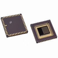
IC SENSOR IMAGE VGA MONO 48-CLCC
Manufacturer
Eastman Kodak Company
Type
CMOS Imagingr
Datasheet
1.KAC-9618.pdf
(43 pages)
Specifications of KAC-9618
Pixel Size
7.5µm x 7.5µm
Active Pixel Array
648H x 488V
Frames Per Second
30
Voltage - Supply
3.3V
Package / Case
48-CLCC
Lead Free Status / RoHS Status
Lead free / RoHS Compliant
Other names
LM9618IEA
LM9618IEA
LM9618IEA
Available stocks
Company
Part Number
Manufacturer
Quantity
Price
Company:

Part Number:
KAC-9618
Manufacturer:
IXYS
Quantity:
2 100


IMAGE SENSOR SOLUTIONS
Functional Description
2.0
The integrated timing and control circuit allows any size window
in any position within the active region of the array to be read out
with a 1x1 pixel resolution. The window read out is called the
“Display Window”.
A “Scan Window” must be defined first, by programing the start
and end row addresses as shown in Figure 13. Four coordinates
(start row address, start column address, end row address &
end column address) are programmed to define the size and
location of the “Display Window” to be read out (see Figure 13).
Notes:
Note a:
Note b:
Note c:
Note d:
2.1
Two registers (SROWS & SROWE) are provided to program the
size of the scan window. The start and end row address of the
scan window is given by:
Where:
This mode is provided for backward compatibility with the KAC-
9627 and KAC-9617 CMOS image sensors.
end address
www.kodak.com/go/imagers 585-722-4385
start address
end address
display row
display row
scan row
start address
scan row start address = (2* SwStartRow) + SwLsb
scan row end address = (2* SwEndRow) + 1 + SwLsb
SwStartRow
SwEndROW
SwLsb
scan row
WINDOWING
Programming the scan window (mode a, default)
The “Display Window” must always be defined within
the “Scan Window”.
By default the “Display Window” is the complete array.
The end column address of the “Display Window”
cannot be smaller than 3F hex (63 Decimal).
New “Scan Window” coordinates only take effect at
the beginning of the first frame after the UpdateSet-
tings bit is set in the UPDATE register.
is the contents of the Scan Window start row
register (SROWS)
is the contents of the Scan Window end row reg-
ister (SROWE)
is bit 6 of the Display Window LSB register
(DWLSB)
Figure 13. Windowing
start address
display col
Display Window
(continued)
Active Pixel Array
end address
display col
Scan Window
12
2.2
To programme the scan window in mode b, bit 0 of the Scan
Window LSB Register (SROWLSB). In this mode the binary
value of scan window start and end row addresses are given by
Where:
2.3
After the “Scan Window” coordinates have been programmed,
the UpdateSettings bit in the UPDATE register should be set.
The timing and control circuit will set the new “Scan Window” at
beginning of the next frame and reset the UpdateSettings bit in
the UPDATE register.
2.4
Five register (DROWS, DROWE, DCOLS, DCOLE and DWLSB)
are provided to program the display window as described in the
register section of this datasheet.
scan row start address (bin) = [SwStartRow, SwStartRowLsb]
scan row end address (bin) = [SwEndRow, SwEndRowLsb]
SwStartRow
SwEndRow
SwStartRowLsb
SwEndRowLsb
Programming the scan window (mode b)
Updating the Scan Window
Programming the Display Window
is the contents of the Scan Window start row
register (SROWS)
is the contents of the Scan Window end row reg-
ister (SROWE)
is the contents of bit 7 of the Scan Window Row
LSB register (SROWLSB)
is the contents of bit 6 of the Scan Window Row
LSB register (SROWLSB)
Email:imagers@kodak.com
Related parts for KAC-9618
Image
Part Number
Description
Manufacturer
Datasheet
Request
R

Part Number:
Description:
IC PROCESSOR IMAGE DGTL REALTIME
Manufacturer:
Eastman Kodak Company

Part Number:
Description:
HEADBOARD FOR KAC-9618
Manufacturer:
Eastman Kodak Company

Part Number:
Description:
HEADBOARD FOR KAC-9619
Manufacturer:
Eastman Kodak Company

Part Number:
Description:
HEADBOARD FOR KAC-9628
Manufacturer:
Eastman Kodak Company

Part Number:
Description:
HEADBOARD FOR KAC-9630
Manufacturer:
Eastman Kodak Company

Part Number:
Description:
HEADBOARD FOR KAC-9637
Manufacturer:
Eastman Kodak Company

Part Number:
Description:
HEADBOARD FOR KAC-9638
Manufacturer:
Eastman Kodak Company

Part Number:
Description:
HEADBOARD FOR KAC-9647
Manufacturer:
Eastman Kodak Company

Part Number:
Description:
HEADBOARD FOR KAC-9648
Manufacturer:
Eastman Kodak Company
Part Number:
Description:
HEADBOARD FOR KAC-9627
Manufacturer:
Eastman Kodak Company
Part Number:
Description:
KIT EVALUATION SENSOR KAC-9618
Manufacturer:
Eastman Kodak Company
Part Number:
Description:
KIT EVALUATION SENSOR KAC-9638
Manufacturer:
Eastman Kodak Company
Part Number:
Description:
KIT EVALUATION SENSOR KAC-9628
Manufacturer:
Eastman Kodak Company
Part Number:
Description:
KIT EVALUATION SENSOR KAC-9637
Manufacturer:
Eastman Kodak Company
Part Number:
Description:
KIT EVALUATION SENSOR KAC-9647
Manufacturer:
Eastman Kodak Company