ADNB-7051-EV Avago Technologies US Inc., ADNB-7051-EV Datasheet - Page 4
ADNB-7051-EV
Manufacturer Part Number
ADNB-7051-EV
Description
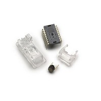
OPT SENSOR BUNDLE SET FOR A7050
Manufacturer
Avago Technologies US Inc.
Specifications of ADNB-7051-EV
Description/function
Laser Mouse Bundle
Interface Type
SPI
Product
Display Modules
Touch Panel
No Touch Panel
For Use With/related Products
ADNS-7050
Lead Free Status / RoHS Status
Lead free / RoHS Compliant
Lead Free Status / RoHS Status
Lead free / RoHS Compliant, Lead free / RoHS Compliant


DIMENSIONS IN MILLIMETERS (INCHES).
4
Figure 3. Recommended PCB mechanical cutouts and spacing.
Assembly Recommendation
•
•
•
•
•
•
OPTICAL NAVIGATION CENTER
Insert the sensor and all other electrical components
into the application PCB (main PCB board and VCSEL
PCB board).
Wave-solder the entire assembly in a no-wash
solder process utilizing a solder fixture. The solder
fixture is needed to protect the sensor during the
solder process. It also sets the correct sensor-to -PCB
distance, as the lead shoulders do not normally rest
on the PCB surface. The fixture should be designed to
expose the sensor leads to solder while shielding the
optical aperture from direct solder contact.
Place the lens onto the base plate.
Remove the protective kapton tape from the optical
aperture of the sensor. Care must be taken to keep
contaminants from entering the aperture.
Insert the PCB assembly over the lens onto the base
plate. The sensor aperture ring should self-align to the
lens. The optical position reference for the PCB is set
by the base plate and lens. Note that the PCB motion
due to button presses must be minimized to maintain
optical alignment.
Remove the protective cap from the VCSEL.
(0.496)
12.6
(0.433)
11.0
PIN 1 HOLE
(0.248)
6.3
(0.063)
1.6
(0.070)
1.78
0
(0.584)
0
14.84
(0.596)
15.15
(0.035)
(0.008)
(0.984)
0.89
0.2
25.0
(1.417)
36.0
Design Considerations for Improving ESD Performance
For improved electrostatic discharge performance, typi-
cal creepage and clearance distance are shown in the
table below. Assumption: base plate construction as per
the Avago Technologies supplied IGES file and ADNS-
6130-001 trim lens (or ADNS-6120 round lens).
Typical Distance
Creepage
Clearance
Note that the lens material is polycarbonate and therefore,
cyanoacrylate based adhesives or other adhesives that may damage
the lens should NOT be used.
•
•
•
•
18X ∅ 0.75
Insert the VCSEL assembly into the lens.
Slide the clip in place until it latches. This locks the
VCSEL and lens together.
Tune the laser output power from the VCSEL to meet
the Eye Safe Class I Standard as detailed in the LASER
Power Adjustment Procedure.
in the top case (or other area) to press down onto the
sensor to ensure the sensor and lens are interlocked
to the correct vertical height.
Install the mouse top case. There must be a feature
(0.030)
6X R 0.75
(0.496)
12.6
RECOMMENDED
(0.030)
2 mm MAX. COMPONENT
HEIGHT RECOMMENDED FINGER
CLEARANCE ZONE (BOTH SIDES)
(0.890)
22.6
2 mm MAX. COMPONENT
HEIGHT CLEAR ZONE
MAX.
(0.000)
Millimeters
12.0
2.1
0
(0.394)
10.0
Related parts for ADNB-7051-EV
Image
Part Number
Description
Manufacturer
Datasheet
Request
R

Part Number:
Description:
OPTICAL MOUSE EVALUATION KIT
Manufacturer:
Avago Technologies US Inc.
Datasheet:

Part Number:
Description:
Display Modules & Development Tools Bundle w/Trim Lens
Manufacturer:
Avago Technologies US Inc.

Part Number:
Description:
Display Modules & Development Tools Bundle w/Trim Lens
Manufacturer:
Avago Technologies US Inc.

Part Number:
Description:
Display Modules & Development Tools Mouse sensor
Manufacturer:
Avago Technologies US Inc.
Part Number:
Description:
Display Modules & Development Tools Mouse sensor
Manufacturer:
Avago Technologies US Inc.

Part Number:
Description:
Display Modules & Development Tools Bundle w/Trim Lens
Manufacturer:
Avago Technologies US Inc.

Part Number:
Description:
Display Modules & Development Tools Sensor+Round Lens
Manufacturer:
Avago Technologies US Inc.
Part Number:
Description:
Display Modules & Development Tools Mouse sensor
Manufacturer:
Avago Technologies US Inc.

Part Number:
Description:
Display Modules & Development Tools Mouse sensor
Manufacturer:
Avago Technologies US Inc.

Part Number:
Description:
Display Modules & Development Tools Bundle w/Trim Lens
Manufacturer:
Avago Technologies US Inc.

Part Number:
Description:
OPTOCOUPLER GATE DRV 2A 16-SOIC
Manufacturer:
Avago Technologies US Inc.
Datasheet:
Part Number:
Description:
OPTOCOUPLER 2CH 2.5A 16-SOIC
Manufacturer:
Avago Technologies US Inc.
Datasheet:

Part Number:
Description:
OPTOCOUPLER GATE DRV 0.4A 16SOIC
Manufacturer:
Avago Technologies US Inc.
Datasheet:

Part Number:
Description:
OPTOCOUPLER 2.0A 250KHZ 8-DIP
Manufacturer:
Avago Technologies US Inc.
Datasheet:

Part Number:
Description:
OPTOCOUPLER 2.0A 250KHZ GW 8-SMD
Manufacturer:
Avago Technologies US Inc.
Datasheet: