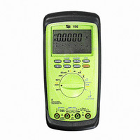
196 TPI (Test Products Int), 196 Datasheet - Page 11
196
Manufacturer Part Number
196
Description
DMM AUTO-RANGE 0-24MA OUTPUT
Manufacturer
TPI (Test Products Int)
Series
190r
Type
Digital (DMM)r
Specifications of 196
Includes
Battery, Test Leads
Style
Handheld
Display Digits
4.75
Display Type
LCD, Bar Graph
Display Count
50000
Function
Voltage, Current, Resistance
Functions, Extra
Continuity, Diode Test
Features
Auto Off, Backlight, Hold, Min/Max, RS-232 Port, Sleep
Ranging
Auto/Manual
Response
Average
Lead Free Status / RoHS Status
Vendor undefined / Vendor undefined
Other names
196TPI
196TPI
290-1425
TPI 196
TPI196
196TPI
290-1425
TPI 196
TPI196
Available stocks
Company
Part Number
Manufacturer
Quantity
Price

Company:
Part Number:
196-015-112-001
Manufacturer:
NorComp Inc.
Quantity:
457
Company:
Part Number:
196-015-112-031
Manufacturer:
NorComp Inc.
Quantity:
457
Company:
Part Number:
196-015-112-551
Manufacturer:
NorComp Inc.
Quantity:
457
Company:
Part Number:
196-015-113L001
Manufacturer:
NorComp Inc.
Quantity:
457


19
b. Measuring AC Volts
Instrument set-up:
FUNCTION
CAUTION
Do not attempt to make a voltage measurement if a test
lead is plugged in the A or umA input jack. Instrument
damage and/or personal injury may result.
Do not attempt to make a voltage measurement of more
than 750V(1000V-Only 194) or of a voltage level than is
unknown.
Measurement Procedure:
1. Disconnect power to circuit to be measured.
2. Plug black test lead into
3. Plug red test lead into the
4. Set the rotary switch to the
5. Connect test leads to circuit to be measured.
6. Reconnect power to circuit to be measured.
7. Read the voltage on the LCD.
voltage to be easured.
WARNING!
BLACK
TEST LEAD TEST LEAD
COM
RED
COM
MINIMUM
READING
0.0001V
input jack.
function depending on the
input jack.
MAXIMUM
READING
750.0V
1000V(Only 194)
c. Measuring DC Amps
Instrument set-up:
FUNCTION
CAUTION
Do not attempt to make a current measurement with the
test leads connected in parallel with the circuit to be
tested. Test leads must be connected in series with the
circuit.
Do not attempt to make a current measurement of circuits
with more than 600V(1000V-Only 194) present. Instrument
damage and/or personal injury may result.
Measurement Procedure:
1. Disconnect power to circuit to be measured.
2. Plug black test lead into the
3. Plug red test lead into the
4. Set the rotary switch to the
5. Connect the test leads in series to the circuit to be
6. Reconnect power to circuit to be measured.
7. Read the current on the LCD.
depending on the value of current to be measured.
measured.
WARNING!
BLACK
TEST LEAD
COM
COM
mA
A
RED
TEST LEAD
COM
or
MINIMUM
READING
or
0.001mA
0.0001A
input jack.
input jack
function.
10.000A
MAXIMUM
READING
500.00mA
20