BK2534 B&K Precision, BK2534 Datasheet - Page 29
BK2534
Manufacturer Part Number
BK2534
Description
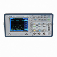
OSCOPE 60MHZ DIGITAL STORAGE
Manufacturer
B&K Precision
Type
Bench, Digitalr
Specifications of BK2534
Includes
Probes, Software, USB Cable
Bandwidth
60MHz
Channels
Dual
Display Type
LCD - Color
Features
Software Controllable, USB Port, Waveform Capture
Probe Type
PR-37A x1/x10/Ref Probes (2)
Sampling Rate (per Second)
400MSa/s
Input Impedance
1M - 19pF
Rise Time (typ)
5.83nS
Voltage - Input, Max
400Vpeak
Voltage - Supply
100 ~ 240VAC
Lead Free Status / RoHS Status
Not applicable / Not applicable


Trigger Level Control
Use the trigger level control knob to adjust the trigger level.
This is the voltage level on the trigger waveform that causes
a trigger event. When you change the trigger level, a
horizontal line temporarily appears to show you the trigger
level on the screen. After the line disappears, the trigger level
is marked with a small left arrow.
Auto and Normal Trigger Modes
Press the trigger MENU key to display the TRIGGER menu
and press the Mode softkey to select Auto or Normal trigger
mode.
Note: The Auto and Normal trigger mode are unavailable
Auto mode
Use the auto trigger mode for signals other than low
repetitive-rate signals and for unknown signal levels. To
display a DC signal, you must use Auto trigger mode since
there is no edge to trigger on.
When you press the RUN/STOP key to start acquiring a
waveform, the oscilloscope first fills the pre-trigger buffer. It
then starts to search for a trigger after the pre-trigger buffer is
filled and continues to flow data through this buffer while it
searches for the trigger. While searching for the trigger, if the
oscilloscope overflows the pre-trigger buffer, the first data put
into the buffer is the first pushed out. When a trigger is found,
when the Video trigger type is selected.
Basic Operation
57
58
Basic Operation
the pre-trigger buffer will contain the events that occurred just
before the trigger. If no trigger is found, the oscilloscope
generates a trigger and displays the data as though a trigger
had occurred. In this case, the background of the Auto
indicator at the top of the display will flash, indicating that the
oscilloscope auto triggered.
When you press the SINGLE key, the oscilloscope will fill the
pre-trigger buffer and continue to flow data through the
pre-trigger buffer until the Auto trigger overrides the
searching and forces a trigger. At the end of the trace, the
oscilloscope will stop and display the results.
Normal mode
Use Normal trigger mode for low repetitive-rate signals or
when Auto trigger is not required.
In Normal mode the oscilloscope must fill the pre-trigger
buffer with data before it will begin searching for a trigger
event. While searching for the trigger, if the oscilloscope
overflows the pre-trigger buffer; the first data put into the
buffer is the first pushed out.
When the trigger event is found, the oscilloscope will fill the
post-trigger buffer and display the results. If the acquisition
was initiated by RUN/STOP, the process repeats. If the
acquisition was initiated by SINGLE, then the acquisition
stops.