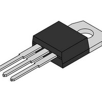
MBR20H100CT ON Semiconductor, MBR20H100CT Datasheet - Page 5

MBR20H100CT
Manufacturer Part Number
MBR20H100CT
Description
Schottky (Diodes & Rectifiers) 20A 100V H-Series
Manufacturer
ON Semiconductor
Series
SWITCHMODE™r
Datasheet
1.MBR20H100CT.pdf
(7 pages)
Specifications of MBR20H100CT
Product
Schottky Diodes
Peak Reverse Voltage
100 V
Forward Continuous Current
10 A
Max Surge Current
250 A
Configuration
Dual Common Cathode
Forward Voltage Drop
0.84 V @ 20 A
Maximum Reverse Leakage Current
4.5 uA
Operating Temperature Range
+ 175 C
Mounting Style
Through Hole
Package / Case
TO-220AB
Voltage - Forward (vf) (max) @ If
770mV @ 10A
Current - Reverse Leakage @ Vr
4.5µA @ 100V
Current - Average Rectified (io) (per Diode)
10A
Voltage - Dc Reverse (vr) (max)
100V
Reverse Recovery Time (trr)
-
Diode Type
Schottky
Speed
Fast Recovery =< 500ns, > 200mA (Io)
Diode Configuration
1 Pair Common Cathode
Mounting Type
Through Hole
Lead Free Status / RoHS Status
Lead free / RoHS Compliant
Available stocks
Company
Part Number
Manufacturer
Quantity
Price
Company:
Part Number:
MBR20H100CT
Manufacturer:
VISHAY0
Quantity:
49
Company:
Part Number:
MBR20H100CT
Manufacturer:
ON
Quantity:
12 500
Part Number:
MBR20H100CT
Manufacturer:
ON/安森美
Quantity:
20 000
Company:
Part Number:
MBR20H100CT-E1
Manufacturer:
SAM
Quantity:
1
Part Number:
MBR20H100CT-E1
Manufacturer:
BCD
Quantity:
20 000
Company:
Part Number:
MBR20H100CT-E3/45
Manufacturer:
Vishay Semiconductors
Quantity:
135
Company:
Part Number:
MBR20H100CTF-E1
Manufacturer:
BCD
Quantity:
4 250
Part Number:
MBR20H100CTG
Manufacturer:
ON/安森美
Quantity:
20 000
Part Number:
MBR20H100CTG-E3/45
Manufacturer:
VISHAY/威世
Quantity:
20 000
Figure 11 was used to demonstrate the controlled avalanche
capability of this device. A mercury switch was used instead
of an electronic switch to simulate a noisy environment
when the switch was being opened.
up linearly; and energy is stored in the coil. At t
is opened and the voltage across the diode under test begins
to rise rapidly, due to di/dt effects, when this induced voltage
reaches the breakdown voltage of the diode, it is clamped at
BV
which now starts to decay linearly through the diode, and
goes to zero at t
is opened; and calculating the energy that is transferred to
the diode it can be shown that the total energy transferred is
equal to the energy stored in the inductor plus a finite amount
of energy from the V
breakdown (from t
component resistances. Assuming the component resistive
The unclamped inductive switching circuit shown in
When S
By solving the loop equation at the point in time when S
0.001
DUT
0.01
0.000001
0.1
10
1
and the diode begins to conduct the full load current
0.05
0.01
D = 0.5
0.2
0.1
SINGLE PULSE
1
MERCURY
SWITCH
is closed at t
2
S
.
1
0.00001
Figure 11. Test Circuit
1
DD
to t
0
power supply while the diode is in
the current in the inductor I
Figure 10. Thermal Response Junction−to−Case for MBRF20H100CT
2
I
) minus any losses due to finite
L
0.0001
+V
10 mH COIL
DUT
DD
I
D
0.001
1
V
the switch
D
L
http://onsemi.com
ramps
t
1
0.01
, TIME (sec)
1
5
elements are small Equation (1) approximates the total
energy transferred to the diode. It can be seen from this
equation that if the V
breakdown voltage of the device, the amount of energy
contributed by the supply during breakdown is small and the
total energy can be assumed to be nearly equal to the energy
stored in the coil during the time when S
Equation (2).
0.1
W
t
W
EQUATION (1):
EQUATION (2):
0
AVAL
AVAL
Figure 12. Current−Voltage Waveforms
[ 1
[ 1
2
2
1
I
LI
LI
L
2
LPK
2
LPK
DD
voltage is low compared to the
BV
10
BV
DUT
DUT
P
t
DUTY CYCLE, D = t
1
(pk)
V
DD
BV
DUT
I
D
100
t
1
1
t
2
was closed,
t
2
1
V
/t
DD
2
1000
t


