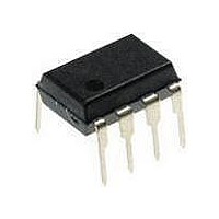
TISP61512P-S Bourns Inc., TISP61512P-S Datasheet - Page 8

TISP61512P-S
Manufacturer Part Number
TISP61512P-S
Description
Sidacs
Manufacturer
Bourns Inc.
Datasheet
1.TISP61512P-S.pdf
(9 pages)
Specifications of TISP61512P-S
Breakover Current Ibo Max
5 A
Rated Repetitive Off-state Voltage Vdrm
100 V
Off-state Leakage Current @ Vdrm Idrm
0.005 mA
Forward Voltage Drop
4 V
Mounting Style
Through Hole
Package / Case
PDIP-8
Lead Free Status / RoHS Status
Lead free / RoHS Compliant
When the TISP switches into the on-state it has a very low impedance. As a result, although the surge wave shape may be defined in terms of
open circuit voltage, it is the current waveshape that must be used to assess the TISP surge requirement. As an example, the CCITT IX K17
1.5 kV, 10/700 µs surge is changed to a 38 A 5/310 µs waveshape when driving into a short circuit. The impulse generators used for rated
values are tabulated below
Figures 4. and 5. show how the TISP61511D limits negative and positive overvoltages. Negative overvoltages (Figure 4.) are initially clipped
close to the SLIC negative supply rail value (V
into a low voltage on-state condition. As the overvoltage subsides the high holding current of the crowbar prevents dc latchup. The protection
voltage will be the sum of the gate supply (V
is a long connection between the gate decoupling capacitor, C, and the gate terminal. During the initial rise of a fast impulse, the gate current
(I
minimize this inductive voltage increase of protection voltage, the length of the capacitor to gate terminal tracking should be minimized.
Inductive voltages in the protector cathode wiring can increase the protection voltage. These voltages can be minimized by routing the SLIC
connection through the protector as shown in Figure 3.
Positive overvoltages (Figure 5.) are clipped to ground by forward conduction of the diode section in protector (Th5). Fast rising impulses will
cause short term overshoots in forward voltage (V
The thyristor protection voltage, (V
dent on the rate of current rise, di/dt, when the TISP is clamping the voltage in its breakdown region. The diode protection voltage, known as
the forward recovery voltage, (V
generator voltage rate of rise, dv/dt, and the circuit resistance. The impulse generators used for characterizing the protection voltages are
tabulated on the next page.
Impulse Generators used for Rated Values
Impulse Conditions (Continued)
G
) is the same as the cathode current (I
TR-NWT-001089
TR-NWT-001089
ETS 300 047-1
K17, K20, K21
RLM88/I3124
Standard
TISP61511D Gated Protectors
Figure 4. Negative Overvoltage Condition
I
K
PROTECTOR
Peak Voltage
61511D
SLIC
TISP
220 nF
Setting
2500
3000
1600
1600
1000
C
V
Th5
FRM
(BO)
) is dependent on the rate of current rise, di/dt. An estimate of the circuit di/dt can be made from the surge
I
G
) increases under lightning surge conditions due to thyristor regeneration time. This increase is depen-
K
). Rates of 70 A/µs can cause inductive voltages of 0.7 V in 2.5 cm of printed wiring track. To
V
SLIC
Wave Form
AI6XAB
BAT
BAT
10/1000
Voltage
0.5/700
10/700
1.2/50
BAT
2/10
) and the peak gate-cathode voltage (V
µs
). If sufficient current is available from the overvoltage, then the protector (Th5) will crowbar
FRM
).
Source Impedance
Generator Fictive
38
40
40
10
Y
5
Customers should verify actual device performance in their specific applications.
Figure 5. Positive Overvoltage Condition
Series Resistance
GK(BO)
External
). The protection voltage will be increased if there
I
F
10
23
Y
0
0
0
PROTECTOR
61511D
SLIC
TISP
220 nF
Specifications are subject to change without notice.
Th5
Peak Current
170
80
40
40
30
A
V
JULY 1995 — REVISED JULY 2008
SLIC
AI6XAC
BAT
Wave Form
Current
10/1000
0.2/310
0.6/18
5/310
2/10
µs


