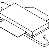
MRF8P26080HR3 Freescale Semiconductor, MRF8P26080HR3 Datasheet - Page 2

MRF8P26080HR3
Manufacturer Part Number
MRF8P26080HR3
Description
RF MOSFET Power HV8 2.6GHZ 80W NI780-4
Manufacturer
Freescale Semiconductor
Datasheet
1.MRF8P26080HR3.pdf
(14 pages)
Specifications of MRF8P26080HR3
Transistor Polarity
N-Channel
Configuration
Single
Package / Case
NI-780-4
Lead Free Status / RoHS Status
Lead free / RoHS Compliant
2
MRF8P26080HR3 MRF8P26080HSR3
Table 2. Thermal Characteristics
Table 3. ESD Protection Characteristics
Table 4. Electrical Characteristics
Off Characteristics
On Characteristics
Functional Tests
P
ACPR measured on 3.84 MHz Channel Bandwidth @ ±5 MHz Offset.
Typical Broadband Performance
V
CCDF. ACPR measured in 3.84 MHz Channel Bandwidth @ ±5 MHz Offset.
out
GSB
Thermal Resistance, Junction to Case
Human Body Model (per JESD22--A114)
Machine Model (per EIA/JESD22--A115)
Charge Device Model (per JESD22--C101)
Zero Gate Voltage Drain Leakage Current
Zero Gate Voltage Drain Leakage Current
Gate--Source Leakage Current
Gate Threshold Voltage
Gate Quiescent Voltage
Drain--Source On--Voltage
Power Gain
Drain Efficiency
Output Peak--to--Average Ratio @ 0.01% Probability on CCDF
Adjacent Channel Power Ratio
1. MTTF calculator available at http://www.freescale.com/rf. Select Software & Tools/Development Tools/Calculators to access MTTF
2. Refer to AN1955, Thermal Measurement Methodology of RF Power Amplifiers. Go to http://www.freescale.com/rf. Select
3. Exceeds recommended operating conditions. See CW operation data in Maximum Ratings table.
4. Each side of device measured separately.
5. Part internally matched both on input and output.
6. Measurement made with device in a Symmetrical Doherty configuration.
Case Temperature 77°C, 14 W CW, 28 Vdc, I
Case Temperature 90°C, 80 W CW
(V
(V
(V
(V
(V
(V
= 14 W Avg., f = 2620 MHz, Single--Carrier W--CDMA, IQ Magnitude Clipping, Input Signal PAR = 7.5 dB @ 0.01% Probability on CCDF.
calculators by product.
Documentation/Application Notes -- AN1955.
= 1.3 Vdc, P
DS
DS
GS
DS
DD
GS
= 65 Vdc, V
= 28 Vdc, V
= 5 Vdc, V
= 10 Vdc, I
= 28 Vdc, I
= 10 Vdc, I
(5,6)
out
DS
D
DA
D
(4)
(4)
GS
GS
= 14 W Avg., Single--Carrier W--CDMA, IQ Magnitude Clipping, Input Signal PAR = 7.5 dB @ 0.01% Probability on
= 75 μAdc)
= 0.75 Adc)
(In Freescale Doherty Production Test Fixture, 50 ohm system) V
= 0 Vdc)
= 300 mAdc, Measured in Functional Test)
= 0 Vdc)
= 0 Vdc)
Characteristic
Frequency
2570 MHz
2595 MHz
2620 MHz
(6)
(In Freescale Doherty Characterization Test Fixture, 50 ohm system) V
(3)
Test Methodology
(T
, 28 Vdc, I
Characteristic
A
= 25°C unless otherwise noted)
DQA
DQA
= 300 mA, V
= 300 mA, V
GSB
GSB
= 1.3 Vdc, 2620 MHz
= 1.3 Vdc, 2620 MHz
Symbol
V
V
V
ACPR
I
I
I
PAR
DS(on)
GS(th)
GS(Q)
G
DSS
DSS
GSS
η
ps
D
(dB)
15.4
15.2
15.0
G
ps
DD
= 28 Vdc, I
13.8
34.0
Min
1.0
1.9
0.1
6.4
—
—
—
—
39.1
38.2
36.9
(%)
η
DQA
D
Symbol
R
θJC
= 300 mA, V
--40.0
0.23
15.0
36.9
Typ
1.8
2.6
6.8
—
—
—
DD
= 28 Vdc, I
Output PAR
Freescale Semiconductor
IV (Minimum)
2 (Minimum)
A (Minimum)
(dB)
Value
6.8
6.8
6.8
Class
GSB
0.88
0.56
--33.0
Max
16.8
2.5
3.4
0.3
10
—
—
1
1
(1,2)
DQA
= 1.3 Vdc,
RF Device Data
= 300 mA,
(continued)
ACPR
(dBc)
--33.6
--36.0
--40.0
μAdc
μAdc
μAdc
°C/W
Unit
Unit
Vdc
Vdc
Vdc
dBc
dB
dB
%


