A7B-C Omron, A7B-C Datasheet - Page 24
A7B-C
Manufacturer Part Number
A7B-C
Description
CONNECTOR
Manufacturer
Omron
Type
Connectorr
Series
A7BS, A7BLr
Specifications of A7B-C
Accessory Type
Connector
Illumination
Not Illuminated
Height
20.5 mm
Length
37 mm
Mounting Style
Snap On
Termination Style
Solder
Width
7.8 mm
Body Orientation
Straight
Gender
PL
Pitch (mm)
2.54mm
Number Of Contact Rows
2
Lead Free Status / RoHS Status
Lead free / RoHS Compliant
For Use With/related Products
SW266 ~ SW269
For Use With
SW266 - SWITCH THUMBWHEEL BLACK BCDSW267 - SWITCH THUMBWHEEL BLACK BCDSW268 - SWITCH THUMBWHEEL EXT BRD BCDSW269 - SWITCH THUMBWHEEL EXT BRD +,-DIS
Lead Free Status / Rohs Status
Lead free / RoHS Compliant
Other names
A7BC
SW270
SW270


A7j
Precautions
Environment
Do not use where gases are generated (ammonia, chlorine, sulfur
dioxide).
Although Switches are of nearly dust-proof construction, they are
not drip-proof, therefore do not use in areas subject to water or oil
exposure and do not operate with wet or oily hands. (The A7MD has
a dust-proof construction on contact parts, but consider your instal-
lation location carefully. The A7MA is not of dust-proof construc-
tion.)
Provide additional dust-proofing measure when using in sand-ex-
posed areas.
Setting Numbers
Locking Type
Set with the setting button by raising it.
Return the button to its original position after setting. It is then locked
to prevent rotation, and the set numbers will not change accidental-
ly.
Pen-push Type
To set, press the setting button with a ball-point pen or other pointed
object. However, avoid using pencils or mechanical pencils as bro-
ken lead or lead dust may enter and damage the Switch.
Handling
Use alcohol to wipe off dirt and smudges from the molded-plastic
cases. Take care to prevent the alcohol from getting inside.
Do not use thinner or other solutions which might damage the plas-
tic.
When connecting Switches, fit the mating parts together.
When separating Switches, use a screwdriver as shown in the fig-
ure below; disconnect them by releasing the top and bottom hooks.
Do not push the (+) and (–) operating push-buttons at the same time
with undue force.
Terminals for PCB Models
When using terminals for printed circuit boards, make the terminal
insertion holes in the back board (mother board) 1 mm or larger in
diameter.
Do not use excessive force in handling terminals for printed circuit
boards. In particular, take care to avoid dropping them as the termi-
nals might bend or break.
Reference: Terminals can withstand a force of 0.8 g for 1 minute or
The A7MD accommodates only printed circuit boards. When pulling
out the operating surface from the back of the panel, refer to the fig-
ures for panel mounting dimensions. However, it cannot be fas-
tened alone to the panel.
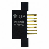
Connectors
Insert Connectors while keeping the arrow pointing up (refer to page
31).
Connector insertion load is about 1.5 kg for each A7B-C.
Setting the Stopper (A7BS-20j-S)
With the A7BS-20j-S, any range can be set outside with the Stop-
per Pin. Insert the Stopper Pin using the following procedure:
Example: To Display the Range 0 to 7
1. Any number within the range of (0 to 7) can be chosen to limit
2. First, insert the Stopper Pin in the hole in front of the lower limit
3. Next, inset the Stopper Pin in the hole past the upper limit (“7”)
4. Confirm that the (+) push-button can no longer be pushed
the numbers displayed in the display window. (In this
example, 8 and 9 are outside of this range.)
(“0”) for the number to be defined.
for the number to be defined. (The Stopper Pins then
surround the exact range to be defined.)
after reaching the upper limit of (“7”).
(3) Stopper Pin (upper limit)
more, and survive bending of 20° without breaking after
returning to original position.
(2) Stopper Pin (lower limit)
(1) Display window
A7j
35
Related parts for A7B-C
Image
Part Number
Description
Manufacturer
Datasheet
Request
R

Part Number:
Description:
Endcap, Ship 1 LFT And 1 RGT
Manufacturer:
Omron
Datasheet:


Part Number:
Description:
Endcap, Ship 1 LFT And 1 RGT
Manufacturer:
Omron
Datasheet:
Part Number:
Description:
SPACER W/DECIMAL POINT
Manufacturer:
Omron
Datasheet:

Part Number:
Description:
G6S-2GLow Signal Relay
Manufacturer:
Omron Corporation
Datasheet:
Part Number:
Description:
Compact, Low-cost, SSR Switching 5 to 20 A
Manufacturer:
Omron Corporation
Datasheet:
Part Number:
Description:
Manufacturer:
Omron Corporation
Datasheet:
Part Number:
Description:
Manufacturer:
Omron Corporation
Datasheet: