PY08-02 Omron, PY08-02 Datasheet - Page 10
PY08-02
Manufacturer Part Number
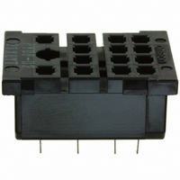
PY08-02
Description
PCB SOCKET FOR MY2(S)
Manufacturer
Omron
Series
MYr
Type
Socketr
Datasheets
1.MY2_DC24_S.pdf
(20 pages)
2.G5SB-1A4_DC5.pdf
(44 pages)
3.MY4-02-DC24.pdf
(17 pages)
4.H3Y-2_AC200-230_10S.pdf
(11 pages)
Specifications of PY08-02
Number Of Positions
8
Mounting Type
Through Hole
Termination Style
PC Pin
Associated Relay Series
H3YN-2, H3YN-21
Number Of Poles
2
Accessory Type
PC Terminal Socket
Socket Mounting
PC Board
Current Rating
7A
Socket Terminals
Through Hole
Voltage Rating
250VAC
No. Of Pins
8
Leaded Process Compatible
Yes
No. Of Contacts
2
Rohs Compliant
Yes
Contact Termination
Through Hole Vertical
Lead Free Status / RoHS Status
Lead free / RoHS Compliant
For Use With/related Products
MY2 Relays
For Use With
MY2N-D2DC6(S) - RELAY GP DPDT 5A 6VDCMY2N-D2DC48(S) - RELAY GP DPDT 5A 48VDCMY2N-D2DC100/110(S) - RELAY GP DPDT 5A 100/110VDCMY2N-CRAC220/240(S) - RELAY GP DPDT 5A 220/240VACMY2N-CRAC110/120(S) - RELAY GP DPDT 5A 110/120VACMY2NAC6(S) - RELAY GP DPDT 5A 6VACMY2NAC200/220(S) - RELAY GP DPDT 5A 200/220VACMY2N1-D2DC100/110(S) - RELAY GP DPDT 5A 100/110VDCMY2IN-D2DC48(S) - RELAY GP DPDT 5A 48VDCMY2IN-D2DC100/110(S) - RELAY GP DPDT 5A 100/110VDCMY2IN-CRAC220/240(S) - RELAY GP DPDT 5A 220/240VACMY2IN-CRAC110/120(S) - RELAY GP DPDT 5A 110/120VACMY2INAC24(S) - RELAY GP DPDT 5A 24VACMY2IN1-D2DC100/110(S) - RELAY GP DPDT 5A 100/110VDCMY2-DDC12(S) - RELAY GP DPDT 5A 12VDCMY2AC100/110(S) - RELAY GP DPDT 5A 100/110VACH3YN-2DC24 - TIMER MINI MULTI-TIME DPDT 24VDCH3YN-2DC125 - TIMR MINI MULTI-TIME DPDT 125VDCH3YN-2DC12 - TIMER MINI MULTI-TIME DPDT 12VDCH3YN-2AC24 - TIMER MINI MULTI-TIME DPDT 24VH3YN-21DC24 - TIMER MINI MULTI-TIME DPDT 24VDCH3YN-21DC125 - TIMR MINI MULTI-TIME DPDT 125VDCH3YN-21DC12 - TIMER MINI MULTI-TIME DPDT 12VDCH3YN-21AC24 - TIMER MINI MULTI-TIME DPDT 24VH3YN-21AC200-230 - TIMER MINI MULTI-TIME DPDTH3YN-2 AC200-230 - RELAY TIMER ANALOG DPDT 0-10 MINZ1135 - RELAY TIMER ANALOG DPDT 0-10HRSZ1134 - RELAY TIMER ANALOG DPDT 0-10 MINMY2N1-DC24(S) - RELAY PWR DPDT 5A 24VDCMY2N1-DC12(S) - RELAY PWR DPDT 5A 12VDCMY2N1-DC100/110S - RELAY PWR DPDT 5A 110VDCMY2N1-D2-DC24(S) - RELAY PWR DPDT 5A 24VDCMY2N1-D2-DC12(S) - RELAY PWR DPDT 5A 12VDCMY2N-DC6(S) - RELAY PWR DPDT 5A 6VDCMY2N-DC48(S) - RELAY PWR DPDT 5A 48VDCZ2884 - RELAY PWR DPDT 5A 24VDCMY2N-DC12(S) - RELAY PWR DPDT 5A 12VDCMY2N-DC100/110(S) - RELAY PWR DPDT 5A 110VDCZ2883 - RELAY PWR DPDT 5A 24VDCMY2N-D2-DC12(S) - RELAY PWR DPDT 5A 12VDCMY2N-AC24(S) - RELAY PWR DPDT 5A 24VACMY2N-AC220/240(S) - RELAY PWR DPDT 5A 240VACMY2N-AC12(S) - RELAY PWR DPDT 5A 12VACZ2882 - RELAY PWR DPDT 5A 120VACMY2IN1-DC24(S) - RELAY PWR DPDT 5A 24VDCMY2IN1-DC12(S) - RELAY PWR DPDT 5A 12VDCMY2IN1-DC100/110S - RELAY PWR DPDT 5A 110VDCMY2IN1-D2-DC24(S) - RELAY PWR DPDT 5A 24VDCMY2IN1-D2-DC12(S) - RELAY PWR DPDT 5A 12VDCMY2IN-DC24(S) - RELAY PWR DPDT 5A 24VDCMY2IN-DC12(S) - RELAY PWR DPDT 5A 12VDCMY2INDC100/110(S) - RELAY PWR DPDT 5A 110VDCMY2IN-D2-DC24(S) - RELAY PWR DPDT 5A 24VDCMY2IN-D2-DC12(S) - RELAY PWR DPDT 5A 12VDCMY2IN-AC220/240S - RELAY PWR DPDT 5A 240VACMY2IN-AC12(S) - RELAY PWR DPDT 5A 12VACMY2IN-AC110/120S - RELAY PWR DPDT 5A 120VACMY2-DC6(S) - RELAY PWR DPDT 5A 6VDCMY2-DC100/110(S) - RELAY PWR DPDT 5A 110VDCMY2-AC6(S) - RELAY PWR DPDT 5A 6VACMY2-AC48/50(S) - RELAY PWR DPDT 5A 48VACMY2-AC220/240(S) - RELAY PWR DPDT 5A 240VACMY2-AC12(S) - RELAY PWR DPDT 5A 12VACZ185 - RELAY PWR 5A DPDT 120VACZ184 - RELAY PWR 5A DPDT 24VACZ183 - RELAY PWR 5A DPDT 48VDCZ182 - RELAY PWR 5A DPDT 24VDCZ181 - RELAY PWR 5A DPDT 12VDC
Lead Free Status / Rohs Status
Lead free / RoHS Compliant
Other names
PY08-02
PY0802
Z2893
PY0802
Z2893
Available stocks
Company
Part Number
Manufacturer
Quantity
Price


Safety Precautions
Refer to Safety Precautions for All Timers.
When selecting a control output, use the H3Y-2 for switching ON and
OFF the power and the H3Y-4 for switching ON and OFF the minute
load.
The operating voltage will increase when using the H3Y in any place
where the ambient temperature is more than 50°C. Supply 90% to
110% of the rated voltages (at 12 VDC: 95% to 110%) when
operating at 45°C or higher.
Do not leave the H3Y in time-up condition for a long period of time
(for example, more than one month in any place where the ambient
temperature is high), otherwise the internal parts (aluminum
electrolytic capacitor) may become damaged. Therefore, the use of
the H3Y with a relay as shown in the following circuit diagram is
recommended to extend the service life of the H3Y.
Do not connect the H3Y as shown in the following circuit diagram on
the right hand side, otherwise the H3Y’s internal contacts different
from each other in polarity may become short-circuited.
Use the following safety circuit when building a self-holding or self-
resetting circuit with the H3Y and an auxiliary relay, such as an MY
Relay, in combination.
Do not use the H3Y in places where there is excessive dust,
corrosive gas, or direct sunlight.
Do not mount more than one H3Y closely together, otherwise the
internal parts may become damaged. Make sure that there is a
space of 5 mm or more between any H3Y Models next to each other
to allow heat radiation.
The internal parts may become damaged if a supply voltage other
than the rated ones is imposed on the H3Y. When more than 100 V is
applied to 12- or 24-VDC models, the internal element (varistor) may
break.
Precautions for EN61812-1
Conformance
The H3Y as a built-in timer conforms to EN61812-1 provided that the
following conditions are satisfied.
Handling
Before dismounting the H3Y from the socket, make sure that no
voltage is imposed on any terminal of the H3Y.
Correct
L
1
ALL DIMENSIONS SHOWN ARE IN MILLIMETERS.
To convert millimeters into inches, multiply by 0.03937. To convert grams into ounces, multiply by 0.03527.
L
2
In the interest of product improvement, specifications are subject to change without notice.
Auxiliary relay such as MY Relay
: H3Y
Auxiliary relay:
MY Relay
Incorrect
L
1
L
2
Wiring
The power supply for the H3Y must be protected with equipment
such as a breaker approved by VDE.
Basic insulation is ensured between the H3Y’s operating circuit and
control output.
Insulation requirement:
Output terminals next to each other on the H3Y-4 or H3Y-4-0 must
have the same polarity.
pollution degree 1 (H3Y-4/-4-0),
pollution degree 2 (H3Y-2/-2-0)
(with a clearance of 1.5 mm and a
creepage distance of 2.5 mm at 240 VAC)
Overvoltage category II,
H3Y
10
Related parts for PY08-02
Image
Part Number
Description
Manufacturer
Datasheet
Request
R

Part Number:
Description:
MY2 SOCKET/SOLDER TERM.
Manufacturer:
Omron
Datasheet:
Part Number:
Description:
MY2 SOCKET WIRE WRAP TERM.
Manufacturer:
Omron
Datasheet:

Part Number:
Description:
G6S-2GLow Signal Relay
Manufacturer:
Omron Corporation
Datasheet:
Part Number:
Description:
Compact, Low-cost, SSR Switching 5 to 20 A
Manufacturer:
Omron Corporation
Datasheet:
Part Number:
Description:
Manufacturer:
Omron Corporation
Datasheet:
Part Number:
Description:
Manufacturer:
Omron Corporation
Datasheet:
Part Number:
Description:
Manufacturer:
Omron Corporation
Datasheet:
Part Number:
Description:
Manufacturer:
Omron Corporation
Datasheet:
Part Number:
Description:
Manufacturer:
Omron Corporation
Datasheet: