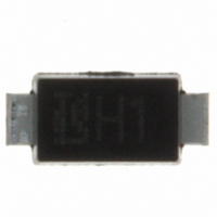
CRH01(TE85L,Q,M) Toshiba, CRH01(TE85L,Q,M) Datasheet - Page 2

CRH01(TE85L,Q,M)
Manufacturer Part Number
CRH01(TE85L,Q,M)
Description
DIODE SWITCHING 200V 1A 3-2A1A
Manufacturer
Toshiba
Specifications of CRH01(TE85L,Q,M)
Voltage - Forward (vf) (max) @ If
980mV @ 1A
Voltage - Dc Reverse (vr) (max)
200V
Current - Average Rectified (io)
1A
Current - Reverse Leakage @ Vr
10µA @ 200V
Diode Type
Standard
Speed
Fast Recovery =< 500ns, > 200mA (Io)
Reverse Recovery Time (trr)
35ns
Mounting Type
Surface Mount
Package / Case
3-2A1A (S-Flat)
Rectifier Type
Switching Diode
Configuration
Single
Peak Rep Rev Volt
200V
Avg. Forward Curr (max)
1A
Rev Curr
10uA
Peak Non-repetitive Surge Current (max)
15A
Forward Voltage
0.98V
Operating Temp Range
-40C to 150C
Package Type
S-FLAT
Rev Recov Time
35ns
Operating Temperature Classification
Automotive
Mounting
Surface Mount
Pin Count
2
Product
Ultra Fast Recovery Rectifier
Reverse Voltage
200 V
Forward Voltage Drop
0.98 V
Recovery Time
35 ns
Forward Continuous Current
1 A
Max Surge Current
15 A
Reverse Current Ir
10 uA
Mounting Style
SMD/SMT
Maximum Operating Temperature
+ 150 C
Minimum Operating Temperature
- 40 C
Lead Free Status / RoHS Status
Lead free / RoHS Compliant
Capacitance @ Vr, F
-
Lead Free Status / Rohs Status
Compliant
Other names
CRH01(TE85L,Q)
CRH01QTR
CRH01QTR
Marking
Standard Soldering Pad
Handling Precaution
The absolute maximum ratings denote the absolute maximum ratings, which are rated values and must not be
exceeded during operation, even for an instant. The following are the general derating methods that we recommend
when you design a circuit with a device.
This rating specifies the non-repetitive peak current in one cycle of a 50-Hz sine wave, condition angle 180.
Therefore, this is only applied for an abnormal operation, which seldom occurs during the lifespan of the device.
We recommend that a device be used at a Tj of below 120°C under the worst load and heat radiation conditions.
Thermal resistance between junction and ambient fluctuates depending on the device’s mounting condition. When
using a device, design a circuit board and a soldering land size to match the appropriate thermal resistance value.
Please refer to the Rectifiers databook for further information.
1.2
Abbreviation Code
V
I
F(AV)
RRM
1.2
H1
:
:
We recommend that the worst case voltage, including surge voltage, be no greater than 80% of the
absolute maximum rating of V
an AC circuit. V
account designing a device at low temperature.
We recommend that the worst case current be no greater than 80% of the absolute maximum rating
of I
set the margin by using an allowable Tamax-I
F(AV)
2.8
. Carry out adequate heat design. If you can’t design a circuit with excellent heat radiation,
Part No.
CRH01
RRM
has a temperature coefficient of 0.1%/°C. Take this temperature coefficient into
Unit: mm
RRM
for a DC circuit and be no greater than 50% of that of V
2
F(AV)
curve.
2006-11-08
CRH01
RRM
for


