H7BX-A AC100-240 Omron, H7BX-A AC100-240 Datasheet
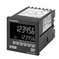
H7BX-A AC100-240
Specifications of H7BX-A AC100-240


Related parts for H7BX-A AC100-240

H7BX-A AC100-240 Summary of contents
Page 1
... NPN transistor output ■ Accessories (Order Separately) Name Model Soft Cover Y92A-72F1 Hard Cover Y92A-72 Terminal Cover (See note.) Y92A-72T Note: Supplied with the H7BX. Be sure to read Safety Precautions on page 25. Supply voltage 1-stage 100 to 240 VAC H7BX-A 24 VAC/ VDC H7BX-AD1 Multifunction Counter 2-stage ...
Page 2
... VAC (50/60 Hz)/ VDC (ripple 20% max.) Ratings Operating voltage range 85% to 110% of rated supply voltage (90% to 110 VDC) H7BX-A/AW: 9.6 VA max. (100 to 240 VAC) Power consumption H7BX-AD1/AWD1 max. (24 VAC), 5.3 W max. ( VDC) Mounting method Flush mounting External connections Screw terminals Degree of protection ...
Page 3
... Dielectric other than the H7BX-A@D1) strength 1,000 VAC, 50/60 Hz for 1 min (H7BX-A@D1) Between control output, power supply, and input circuit: 2,000 VAC, 50/60 Hz for 1 min Between non-continuous contacts: 1,000 VAC, 50/60 Hz for 1 min Between power terminals: 3.0 kV (1.0 kV for 24 VAC/ VDC models) ...
Page 4
... Holds the batch count value at 0 while the reset 2 input is ON. Resets the CP2 present value. Dual counter Counting for CP2 input is disabled while the reset 2 input is ON. 4 Multifunction Counter Reset operation H7BX ● Using as a Tachometer Reads counting signals. CP1, (CP2 input is not CP2 available.) ...
Page 5
... Connections ■ Terminal Arrangement Confirm that the power supply meets specifications before using the H7BX. H7BX External power supply Unused. 15 Key 16 protection OUT H7BX-AD1 External power supply Unused. 15 Key 16 protection OUT (+) Note: Do not use the unused terminals for relay connections. ■ Block Diagram ...
Page 6
... Terminal No. Operates when the transistor turns ON. Operates when the transistor turns ON. Note: When the H7BX is used as a tachometer, the CP2 input and total reset/reset 2 input are not used. No-voltage Input Signal Levels Short-circuit level Transistor ON Residual voltage max. Impedance when ON No-contact (The leakage current when the impedance is 0 ...
Page 7
... Dimensions ■ Counter ● Counter H7BX-A@@ 72 ● Dimensions with Flush Mounting Adapter H7BX-A@@ (The flush mounting adapter is supplied with the H7BX.) 72 ■ Accessories (Order Separately) ● Soft Cover Y92A-72F1 Note: Depending on the operating environment, the condition of resin parts may deteriorate, and may shrink or harden. ...
Page 8
... Value, Display Color, or Key Protect Level Settings other than the basic functions above can be performed with the operation keys. For details on the setting methods, refer to page 10. (H7BX-AW@ only) The settings can be made easily with the DIP switch. For details on the setting methods, refer to page 19. ...
Page 9
... DIP switch. For details on the setting methods, refer to page 10. When performing these settings, always turn OFF pin 1(DIP switch setting) (disabled). Using the H7BX as a Total and Preset Counter, Batch Counter, or Dual Counter The default setting is for a 1-stage preset counter ...
Page 10
... When using the H7BX as a Total and Preset Counter, Batch Counter, or Dual Counter, switch the configuration using the procedure on page 23. ■ Setting Advanced Functions Settings that cannot be performed with the DIP switch are performed with the operation keys. Power ON For details on operations and display in run mode, refer to page 12. The display depends on the configuration used. ...
Page 11
... Red (fixed) grn Green (fixed) r-g Red g-r Green Note: When the H7BX using as a 2-stage counter, this is the status of output 2. Key Protect Level (kypt) Set the key protect level. For details, refer to Key Protect Level on page 24. Multifunction Counter 25). 25 pulses Output ON (See note ...
Page 12
... Set the dual count set value. When the dual count value reaches the dual count set value, signals are output according to the specified output mode. CP1/CP2 Present Value Show the present count values for CP1 and CP2 present values respectively. H7BX ...
Page 13
... The meaning of the H and L symbols in the tables is explained below Symbol 1 DOWN (Decrement) Mode A A Prohibit Prohibit UP/DOWN B: Individual Input Mode Input method No-voltage input Voltage input (NPN input) (PNP input) H Short-circuit 4 VDC L Open VDC H7BX Multifunction Counter must ...
Page 14
... Set value 2 Set value 1 K-1 0 OUT1 OUT2 14 Multifunction Counter Input mode DOWN H7BX One-shot output from OUT1 (The one-shot output time can be set in the range 0.01 to 99.99s.) Self-holding Self-holding One-shot output output output from OUT2 Operation after count completion UP/DOWN ...
Page 15
... The outputs repeat one- shot operation. OUT1 self-holding output turns OFF after the OUT2 one-shot output time. The OUT1 one-shot output time is independent of OUT2. The present value display and OUT1 self-holding output is held until reset/ reset 1 input turns ON. OUT1 and OUT2 are independent. H7BX 15 ...
Page 16
... Do not use the counter function in applications where the count may be completed (again) while the one-shot output is ON. 5. The set values are between 99999 and 999999. 16 Multifunction Counter Input mode UP/DOWN H7BX (The one-shot output time can be set in the range 0.01 to 99.99s.) Self-holding Instanta- ...
Page 17
... Total reset/reset 2 Present value 0 999999 Total count value 0 ● Batch Counter Operation The H7BX has a batch counter separate from the 1-stage preset counter for counting the number of times the count has been completed. Reset 1 Reset 2 (batch counter reset) Set value Present value 0 ...
Page 18
... Present value and output reset. Present value and output reset. Batch count value and batch output Present value, Present value and total count value, output reset. and output reset. H7BX Batch counter Dual counter Batch count Dual count value/batch value/dual count count set value set value Only the CP1 present value is reset ...
Page 19
... Operating Procedures (Tachometer Function) ■ Switching from Counter to Tachometer The H7BX is factory-set to the 2-stage counter configuration. To switch to the tachometer configuration, use the procedure shown on the right. For details, refer to page 23. Note: Hold down the Key and then press the Up 1 Key for at least 1 s. ...
Page 20
... When the H7BX using as a tachometer, switch to the tachometer configuration using the procedure given on page 23. ■ Settings for Advanced Functions Settings that cannot be performed with the DIP switch are performed with the operation keys. Power ON (See note 1.) (See note 2 min min. ...
Page 21
... Set the optimum number of times for the application. Auto-zero Time (avt) ★ possible to set the H7BX so that if there is no pulse for a certain time the display is force-set to 0. This time is called the auto-zero time. Set the auto-zero time to a time slightly longer than the estimated interval between input pulses ...
Page 22
... ON condition for OUT1: Measurement value ON condition for OUT2: Measurement value OUT1 OUT2 ON condition for OUT1: Measurement value ON condition for OUT2: Measurement value OUT1 OUT2 H7BX OUT1 set value OUT2 set value OUT1 set value OUT2 OUT1 set value > OUT2 set value set value ...
Page 23
... Switching between Using a Preset Counter, Total and Preset Counter, Batch Counter, Dual Counter, and Tachometer Select which H7BX configuration to use (i.e., preset counter, total and preset counter, batch counter, dual counter, or tachometer) in the configuration selection mode. The H7BX is also equipped with a DIP switch monitor function, a convenient function that enables the settings of the DIP switch pins to be confirmed using the front display ...
Page 24
... When the key-protect switch is set to ON possible to prevent setting errors by prohibiting the use of certain operation keys by specifying the key protect level (KP-1 to KP-5). The key protect indicator is lit while the key-protect switch is set to ON. Confirm the ON/ OFF status of the key protect switch after the H7BX is mounted to the panel. Level ...
Page 25
... Use the H7BX within the specified ratings for operating temperature and humidity. Temperature rise may shorten the service life of H7BX used near a power supply or other heat-generating objects. Use the H7BX within the specified ratings for vibration, shock, and splashing water. ...
Page 26
... OFF. Water resistance will be lost if the front sheet is peeled off or torn. Do not use the H7BX if the front sheet is missing or torn. Abide by all local ordinances and regulations when disposing of the H7BX. External Power Supply ...
Page 27
... Cancellation; Etc. Orders are not subject to rescheduling or cancellation unless Buyer indemnifies Omron against all related costs or expenses. 10. Force Majeure. Omron shall not be liable for any delay or failure in delivery resulting from causes beyond its control, including earthquakes, fires, floods, strikes or other labor disputes, shortage of labor or materials, accidents to machinery, acts of sabotage, riots, delay in or lack of transportation or the requirements of any government authority ...
Page 28
... Complete “Terms and Conditions of Sale” for product purchase and use are on Omron’s website at www.omron.com/oei – under the “About Us” tab, in the Legal Matters section. ALL DIMENSIONS SHOWN ARE IN MILLIMETERS. To convert millimeters into inches, multiply by 0.03937. To convert grams into ounces, multiply by 0.03527. ...