H7BX-A AC100-240 Omron, H7BX-A AC100-240 Datasheet - Page 3
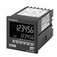
H7BX-A AC100-240
Manufacturer Part Number
H7BX-A AC100-240
Description
1-stg 72x72 Multifunc Counter
Manufacturer
Omron
Datasheet
1.Y92A-72.pdf
(28 pages)
Specifications of H7BX-A AC100-240
Display Type
LCD Backlight
Lead Free Status / Rohs Status
Lead free / RoHS Compliant


■ Characteristics
Note: Check the electrical life expectancy curve.
■ Applicable Standards
Insulation resis-
tance
Dielectric
strength
Impulse with-
stand voltage
Noise immunity
Static immunity
Vibration resis-
tance
Shock resis-
tance
Life expectancy
Weight
Approved
safety
standards
EMC
cURus: UL 508, CSA C22.2 No. 14
EN 61010-1 (IEC 61010-1): Pollution degree 2/overvoltage category II;
EN 61326; VDE 0106 Part 100
(EMI)
Emission Enclosure:
Emission AC mains:
(EMS)
Immunity ESD:
Immunity RF-interference:
Immunity Conducted Disturbance: EN 61000-4-6: 3 V (0.15 to 80 MHz)
Immunity Burst:
Immunity Surge:
Immunity Voltage Dip/Interruption: EN 61000-4-11: 0.5 cycle, 100% (rated voltage)
100 M
current-carrying metal parts, and between non-continuous contacts
Between current-carrying metal parts and non-current-carrying metal parts:
2,000 VAC, 50/60 Hz for 1 min
Between power supply and input circuit: 2,000 VAC, 50/60 Hz for 1 min (for models
other than the H7BX-A@D1)
1,000 VAC, 50/60 Hz for 1 min (H7BX-A@D1)
Between control output, power supply, and input circuit: 2,000 VAC, 50/60 Hz for 1 min
Between non-continuous contacts: 1,000 VAC, 50/60 Hz for 1 min
Between power terminals: 3.0 kV (1.0 kV for 24 VAC/12 to 24 VDC models)
Between current-carrying terminal and exposed non-current-carrying metal parts:
4.5 kV (1.5 kV for 24 VAC/12 to 24 VDC models)
Between power terminals: 1.5 kV
Between input terminals: 600 V
Square-wave noise by noise simulator (Pulse width: 100 ns/1 s, 1-ns rise)
Malfunction: 8 kV
Destruction: 15 kV
Destruction: 10 to 55 Hz, 0.75-mm single amplitude for 4 cycles each in 3 directions (8
min/cycle)
Malfunction: 10 to 55 Hz, 0.50-mm single amplitude for 4 cycles each in 3 directions (8
min/cycle)
Destruction: 294 m/s
Malfunction: 98 m/s
Mechanical: 10,000,000 operations min.
Electrical: 100,000 operations min. (3 A at 250 VAC/30 VDC, resistive load) (See
note.)
Approx. 250 g
min. (at 500 VDC) between current-carrying terminal and exposed non-
2
2
3 times each in 6 directions
3 times each in 6 directions
EN 61326
EN 55011 Group 1 class A
EN 55011 Group 1 class A
EN 61326
EN 61000-4-2: 4 kV contact discharge;
EN 61000-4-3:10 V/m (Amplitude-modulated,
EN 61000-4-4: 2 kV power-line;
EN 61000-4-5: 1 kV line to lines (power and output lines
8 kV air discharge
80 MHz to 1 GHz);
10 V/m (Pulse-modulated,
900 MHz 5 MHz)
1 kV I/O signal-line
(relay outputs));
2 kV line to ground (power and output lines
(relay outputs))
Multifunction Counter
● Electrical Life Expectancy
A current of 0.15 A max. can be switched at
125 VDC (cos = 1) and current of 0.1 A max. can
be switched with L/R = 7 m/s. In both cases, a life of
100,000 operations can be expected.
(Reference Values)
Resistive Load
Inductive Load
1,000
1,000
700
500
300
100
700
500
300
100
70
50
70
50
0
0
250 VAC (cos =0.4)
250 VAC (cos =1)
1
1
H7BX
30 VDC (L/R=7 ms)
30 VDC (cos =1)
2
2
Load current (A)
Load current (A)
3
3
3
4
4
Related parts for H7BX-A AC100-240
Image
Part Number
Description
Manufacturer
Datasheet
Request
R

Part Number:
Description:
G6S-2GLow Signal Relay
Manufacturer:
Omron Corporation
Datasheet:
Part Number:
Description:
Compact, Low-cost, SSR Switching 5 to 20 A
Manufacturer:
Omron Corporation
Datasheet:
Part Number:
Description:
Manufacturer:
Omron Corporation
Datasheet:
Part Number:
Description:
Manufacturer:
Omron Corporation
Datasheet:
Part Number:
Description:
Manufacturer:
Omron Corporation
Datasheet:
Part Number:
Description:
Manufacturer:
Omron Corporation
Datasheet:
Part Number:
Description:
Manufacturer:
Omron Corporation
Datasheet:
Part Number:
Description:
Manufacturer:
Omron Corporation
Datasheet: