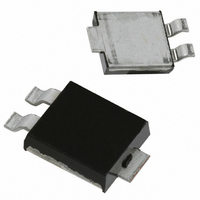
SBM1040-13-F Diodes Inc, SBM1040-13-F Datasheet - Page 3

SBM1040-13-F
Manufacturer Part Number
SBM1040-13-F
Description
DIODE SCHOTTKY 40V 10A PWRMITE3
Manufacturer
Diodes Inc
Specifications of SBM1040-13-F
Voltage - Forward (vf) (max) @ If
510mV @ 10A
Voltage - Dc Reverse (vr) (max)
40V
Current - Average Rectified (io)
10A
Current - Reverse Leakage @ Vr
300µA @ 35V
Diode Type
Schottky
Speed
Fast Recovery =< 500ns, > 200mA (Io)
Capacitance @ Vr, F
700pF @ 4V, 1MHz
Mounting Type
Surface Mount
Package / Case
Powermite®3
Product
Schottky Diodes
Peak Reverse Voltage
40 V
Forward Continuous Current
10 A
Max Surge Current
150 A
Configuration
Single Dual Anode
Forward Voltage Drop
0.51 V
Maximum Reverse Leakage Current
300 uA at 35 V
Operating Temperature Range
- 65 C to + 150 C
Mounting Style
Screw
Lead Free Status / RoHS Status
Lead free by exemption / RoHS Compliant
Reverse Recovery Time (trr)
-
Lead Free Status / Rohs Status
Details
Other names
SBM1040-FDITR
Available stocks
Company
Part Number
Manufacturer
Quantity
Price
Company:
Part Number:
SBM1040-13-F
Manufacturer:
DIODES
Quantity:
500
Company:
Part Number:
SBM1040-13-F
Manufacturer:
TELEDYNE
Quantity:
39
Part Number:
SBM1040-13-F
Manufacturer:
DIODES/美台
Quantity:
20 000
Notes:
Notes:
Ordering Information
Marking Information
POWERMITE is a registered trademark of Microsemi Corporation.
DS30255 Rev. 11 - 3
YYWW(K)
SBM1040
10. R
7. Maximum power dissipation when device mounted on FR-4 substrate, 2”x2”, 2 oz. copper, single-sided, pad layout as per
9. R
6. Maximum power dissipation when device mounted on GETEK substrate, 2”x2”, 2 oz. copper, double-sided, cathode pad
8. R
12. For Lead Free Finish/RoHS Compliant version part number, please add "-F" suffix to the part number above. Example: SBM1040-13-F.
11. For Packaging Details, go to our website at http://www.diodes.com/datasheets/ap02007.pdf.
4
8
7
6
5
3
2
0
1
dimensions 0.75” x 1.0”, anode pad dimensions 0.25” x 1.0”. R
Diodes Inc. suggested pad layout document AP02001 which can be found on our website
at http://www.diodes.com/datasheets/ap02001.pdf. R
dimensions 0.25"x1.0".
dimensions 0.5"x1.0", 2 oz. copper pads.
0
qJA
qJA
qJA
1.5
= 30°C/W when mounted on 2"x2", single-sided, FR-4 board with cathode pad dimensions 0.5"x1.0", anode pad
= 15°C/W when mounted on 2"x2", single-sided, ceramic board with cathode pad dimensions 0.75"x1.0", anode pad
I
I
I
= 90°C/W when mounted on 0.5"x0.625", single-sided, FR-4 board with minimum recommended pad layout.
PK
AV
F(AV)
= 1 (DC)
SBM1040-13
, AVERAGE FORWARD CURRENT (A)
Fig. 5 Forward Power Dissipation
3
SBM1040 = Product type marking code
YYWW = Date code marking
Device
Note 7
YY = Last two digits of year ex: 02 for 2002
WW = Week code 01 to 52
(K) = Factory designator
4.5
= Manufacturers’ code marking
6
(Note 11)
7.5
Note 6
9 10.5 12 13.5 15
qJA
www.diodes.com
in range of 60-75°C/W.
POWERMITEâ3
qJA
3 of 3
Packaging
in range of 15-30°C/W.
120
110
160
150
140
130
100
70
90
80
60
0
Fig. 6 Operating Temperature Derating
Note 10
V , DC REVERSE VOLTAGE (V)
10
R
20
5000/Tape & Reel
Note 8
Shipping
30
Note 9
SBM1040
40


