E3C-S20LW Omron, E3C-S20LW Datasheet - Page 8
E3C-S20LW
Manufacturer Part Number
E3C-S20LW
Description
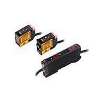
EMITTER COMPONENT OF E3C-S20W
Manufacturer
Omron
Series
E3Cr
Datasheet
1.E3C-GE4.pdf
(16 pages)
Specifications of E3C-S20LW
Sensing Distance
7.874" (200mm)
Sensing Method
Through-Beam
Mounting Type
Bracket Mount
Package / Case
Module, Pre-Wired
Lead Free Status / RoHS Status
Lead free / RoHS Compliant
Current - Supply
-
Voltage - Supply
-
Response Time
-
Output Configuration
-
Lead Free Status / Rohs Status
Lead free / RoHS Compliant
Other names
E3CS20LW
Available stocks
Company
Part Number
Manufacturer
Quantity
Price
Company:

Part Number:
E3C-S20LW
Manufacturer:
VS
Quantity:
18 970


Connection
Amplifier Units
E3C-JC4P
E3C-GE4
E3C-A/C
PF113A
+
Emitter
Receiver
Solid-state output
Connected to the through-beam model
+
−
Shield
Shield
Tb
Emitter
Shield
White
Shield
Emitter
Red
Red
3
4
Ta Tc
2
5
Red
13
1
6
1
5
9
E3C-A/C
11 10
7
100 to 240 VAC
Shield
12
14
Receiver
8
4
8
White
Shield
White
Receiver
9
Response
time
selector
input
Output
Gate input
+
−(Note)
12 to
24 VDC
+ −
−
+
Emitter/
receiver
Solid-state output
Connected to the reflective model
−
+
Shield
Red
Tb
Shield
Shield
White
Red
3
4
Ta Tc
2
5
13
White
Shield
1
5
9
1
6
E3C-A/C
11 10
7
100 to 240 VAC
12
14
4
8
8
9
Emitter/receiver
Response
time
selector
input
Output
Emitter/receiver
Gate input
− (Note)
+
12 to
24 VDC
+ −
−
+
Note: 1. The strip-off length of the
Note: 1. The strip-off length of the
Note: 1. The strip-off length of the
2. The E3C-A does not have
3. L when the gate input 2-9
2. The response time is 1 ms
3. By setting the power
shielded cable should
always be 20 mm max. on
the Receiver side (white)
and 50 mm max. on the
Emitter side (red).
a gate input function.
terminals are connected,
H when they are
disconnected.
shielded cable should
always be 20 mm max. on
the Receiver side (white)
and 50 mm max. on the
Emitter side (red).
shielded cable should
always be 20 mm max. on
the Receiver side (white)
and 50 mm max. on the
Emitter side (red).
when (8) is disconnected,
and 2 ms when (8) is
connected to 0 V (negative
side) of the power supply.
supply terminal (4) to −
and (14) to +, the output
turns "H" when the light is
received. With the E2
mode, the output transistor
turns OFF. By setting (4)
to + and (14) to +, the
output turns "L" when the
light is received. With the
E1 mode, the output
transistor turns ON.
Note
E3C
8
Related parts for E3C-S20LW
Image
Part Number
Description
Manufacturer
Datasheet
Request
R

Part Number:
Description:
PHOTO DIFFUSE 10CM
Manufacturer:
Omron
Datasheet:
Part Number:
Description:
PHOTO AMPLIFIER DC
Manufacturer:
Omron
Datasheet:
Part Number:
Description:
PHOTO BEAM BREAK 1M
Manufacturer:
Omron
Datasheet:
Part Number:
Description:
PHOTO SEPARATE AMP
Manufacturer:
Omron
Datasheet:
Part Number:
Description:
AMPLIFIER PNP SLD. ST.
Manufacturer:
Omron
Datasheet:
Part Number:
Description:
AMP,RAIL MT,ALARM OUTPUT
Manufacturer:
Omron
Datasheet:
Part Number:
Description:
PHOTO FOCUSED TYPE 3CM
Manufacturer:
Omron
Datasheet:
Part Number:
Description:
PHOTO SEPARATE AMP
Manufacturer:
Omron
Datasheet:

Part Number:
Description:
PHOTO MARK SENSOR 1CM
Manufacturer:
Omron
Datasheet:

Part Number:
Description:
PES AMP SLIM DIN MOUNT
Manufacturer:
Omron
Datasheet:

Part Number:
Description:
G6S-2GLow Signal Relay
Manufacturer:
Omron Corporation
Datasheet:
Part Number:
Description:
Compact, Low-cost, SSR Switching 5 to 20 A
Manufacturer:
Omron Corporation
Datasheet: