SD400N20PC Vishay, SD400N20PC Datasheet - Page 3
SD400N20PC
Manufacturer Part Number
SD400N20PC
Description
DIODE 2000V 400A DO-9
Manufacturer
Vishay
Specifications of SD400N20PC
Diode Type
Standard
Voltage - Forward (vf) (max) @ If
1.62V @ 1500A
Voltage - Dc Reverse (vr) (max)
2000V (2kV)
Current - Average Rectified (io)
400A
Current - Reverse Leakage @ Vr
15mA @ 2000V
Speed
Standard Recovery >500ns, > 200mA (Io)
Mounting Type
Chassis, Stud Mount
Package / Case
DO-205AB, DO-9, Stud
Product
Standard Recovery Rectifier
Configuration
Single
Reverse Voltage
2000 V
Forward Voltage Drop
1.62 V at 1500 A
Forward Continuous Current
480 A
Max Surge Current
8640 A
Reverse Current Ir
15000 uA
Mounting Style
Stud
Repetitive Reverse Voltage Vrrm Max
2kV
Forward Current If(av)
400A
Forward Voltage Vf Max
1.62V
Forward Surge Current Ifsm Max
6.94kA
Lead Free Status / RoHS Status
Lead free / RoHS Compliant
Reverse Recovery Time (trr)
-
Capacitance @ Vr, F
-
Lead Free Status / RoHS Status
Lead free / RoHS Compliant, Lead free / RoHS Compliant
Other names
*SD400N20PC
VS-SD400N20PC
VS-SD400N20PC
VSSD400N20PC
VSSD400N20PC
VS-SD400N20PC
VS-SD400N20PC
VSSD400N20PC
VSSD400N20PC


Note
• The table above shows the increment of thermal resistance R
Document Number: 93548
Revision: 17-Apr-08
ΔR
CONDUCTION ANGLE
thJC
CONDUCTION
180°
120°
190
180
170
160
150
140
130
120
110
90°
60°
30°
Fig. 1 - Current Ratings Characteristics
0
50 100 150 200 250 300 350 400 450
Average Forward Current (A)
550
500
450
400
350
300
250
200
150
100
30°
50
S D400N/ R S eries
R
0
thJC
0
SINUSOIDAL CONDUCTION
60°
(DC) = 0.11 K/ W
50 100 150 200 250 300 350 400
Conduction Angle
Average Forward Current (A)
For technical questions, contact: ind-modules@vishay.com
90°
180°
120°
90°
60°
30°
120°
0.020
0.023
0.029
0.042
0.073
Standard Recovery Diodes
180°
Fig. 3 - Forward Power Loss Characteristics
(Stud Version), 400 A
Conduction Angle
S D400N/ R S eries
T = 190°C
J
RMS Limit
thJC
when devices operate at different conduction angles than DC
RECTANGULAR CONDUCTION
10 30 50 70 90 110 130 150 170 190
Maximum Allowable Ambient T emperature (°C)
0.013
0.023
0.031
0.044
0.074
190
180
170
160
150
140
130
120
110
100
Fig. 2 - Current Ratings Characteristics
Vishay High Power Products
0
100 200 300 400 500 600 700
Average Forward Current (A)
30°
60°
TEST CONDITIONS
SD400N/R Series
S D400N/ R S eries
R
T
thJC
90°
J
= T
120°
(DC) = 0.11 K/ W
J
Conduction Period
maximum
180°
DC
www.vishay.com
UNITS
K/W
3
Related parts for SD400N20PC
Image
Part Number
Description
Manufacturer
Datasheet
Request
R

Part Number:
Description:
Standard Recovery Diodes (Stud Version), 400 A
Manufacturer:
VISHAY [Vishay Siliconix]
Datasheet:
Part Number:
Description:
General Purpose Silicon Switching Rectifier
Manufacturer:
Punjab Wireless Systems Ltd.
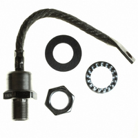
Part Number:
Description:
SD40 distribution box, L-left profile M12-A sockets, built-in control cable
Manufacturer:
SHIELD [SHIELD s.r.l.]
Datasheet:

Part Number:
Description:
357-036-542-201 CARDEDGE 36POS DL .156 BLK LOPRO
Manufacturer:
Vishay
Datasheet:
Part Number:
Description:
357-036-542-201 CARDEDGE 36POS DL .156 BLK LOPRO
Manufacturer:
Vishay
Datasheet:
Part Number:
Description:
357-036-542-201 CARDEDGE 36POS DL .156 BLK LOPRO
Manufacturer:
Vishay
Datasheet:
Part Number:
Description:
357-036-542-201 CARDEDGE 36POS DL .156 BLK LOPRO
Manufacturer:
Vishay
Datasheet:
Part Number:
Description:
357-036-542-201 CARDEDGE 36POS DL .156 BLK LOPRO
Manufacturer:
Vishay
Datasheet:
Part Number:
Description:
357-036-542-201 CARDEDGE 36POS DL .156 BLK LOPRO
Manufacturer:
Vishay
Datasheet:
Part Number:
Description:
357-036-542-201 CARDEDGE 36POS DL .156 BLK LOPRO
Manufacturer:
Vishay
Datasheet:
Part Number:
Description:
357-036-542-201 CARDEDGE 36POS DL .156 BLK LOPRO
Manufacturer:
Vishay
Datasheet:
Part Number:
Description:
357-036-542-201 CARDEDGE 36POS DL .156 BLK LOPRO
Manufacturer:
Vishay
Datasheet:
Part Number:
Description:
357-036-542-201 CARDEDGE 36POS DL .156 BLK LOPRO
Manufacturer:
Vishay
Datasheet:
Part Number:
Description:
357-036-542-201 CARDEDGE 36POS DL .156 BLK LOPRO
Manufacturer:
Vishay
Datasheet:
Part Number:
Description:
357-036-542-201 CARDEDGE 36POS DL .156 BLK LOPRO
Manufacturer:
Vishay
Datasheet: