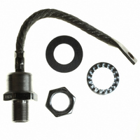
SD400N20PC Vishay, SD400N20PC Datasheet - Page 4
SD400N20PC
Manufacturer Part Number
SD400N20PC
Description
DIODE 2000V 400A DO-9
Manufacturer
Vishay
Specifications of SD400N20PC
Diode Type
Standard
Voltage - Forward (vf) (max) @ If
1.62V @ 1500A
Voltage - Dc Reverse (vr) (max)
2000V (2kV)
Current - Average Rectified (io)
400A
Current - Reverse Leakage @ Vr
15mA @ 2000V
Speed
Standard Recovery >500ns, > 200mA (Io)
Mounting Type
Chassis, Stud Mount
Package / Case
DO-205AB, DO-9, Stud
Product
Standard Recovery Rectifier
Configuration
Single
Reverse Voltage
2000 V
Forward Voltage Drop
1.62 V at 1500 A
Forward Continuous Current
480 A
Max Surge Current
8640 A
Reverse Current Ir
15000 uA
Mounting Style
Stud
Repetitive Reverse Voltage Vrrm Max
2kV
Forward Current If(av)
400A
Forward Voltage Vf Max
1.62V
Forward Surge Current Ifsm Max
6.94kA
Lead Free Status / RoHS Status
Lead free / RoHS Compliant
Reverse Recovery Time (trr)
-
Capacitance @ Vr, F
-
Lead Free Status / RoHS Status
Lead free / RoHS Compliant, Lead free / RoHS Compliant
Other names
*SD400N20PC
VS-SD400N20PC
VS-SD400N20PC
VSSD400N20PC
VSSD400N20PC
VS-SD400N20PC
VS-SD400N20PC
VSSD400N20PC
VSSD400N20PC


SD400N/R Series
Vishay High Power Products
www.vishay.com
4
Fig. 5 - Maximum Non-Repetitive Surge Current
Number Of Equal Amplitude Half Cycle Current Pulses (N)
8000
7000
6000
5000
4000
3000
2000
1
At Any R ated Load Condition And With
S D400N/ R S eries
R ated V
R R M
800
700
600
500
400
300
200
100
Applied Following S urge.
0
0
10
RMS Limit
100 200 300 400 500 600 700
@ 60 Hz 0.0083 s
@ 50 Hz 0.0100 s
Average Forward Current (A)
Initial T = 190°C
180°
120°
DC
90°
60°
30°
For technical questions, contact: ind-modules@vishay.com
J
10000
1000
Standard Recovery Diodes
Fig. 7 - Forward Voltage Drop Characteristics
100
Fig. 4 - Forward Power Loss Characteristics
100
0.5
(Stud Version), 400 A
Conduction Period
S D400N/ R S eries
T = 190°C
J
S D400N/ R S eries
Instantaneous Forward Voltage (V)
1
10 30 50 70 90 110 130 150 170 190
Maximum Allowable Ambient T emperature (°C)
1.5
T = 25°C
T = 190°C
J
J
2
Fig. 6 - Maximum Non-Repetitive Surge Current
9000
8000
7000
6000
5000
4000
3000
2000
1000
2.5
0.01
Maximum Non R epetitive S urge Current
S D400N/ R S eries
Pulse T rain Duration (s)
Versus Pulse T rain Duration.
No Voltage R eapplied
R ated V
0.1
Document Number: 93548
Initial T = 190°C
RRM
R eapplied
Revision: 17-Apr-08
J
1
Related parts for SD400N20PC
Image
Part Number
Description
Manufacturer
Datasheet
Request
R

Part Number:
Description:
Standard Recovery Diodes (Stud Version), 400 A
Manufacturer:
VISHAY [Vishay Siliconix]
Datasheet:
Part Number:
Description:
General Purpose Silicon Switching Rectifier
Manufacturer:
Punjab Wireless Systems Ltd.
Part Number:
Description:
SD40 distribution box, L-left profile M12-A sockets, built-in control cable
Manufacturer:
SHIELD [SHIELD s.r.l.]
Datasheet:

Part Number:
Description:
357-036-542-201 CARDEDGE 36POS DL .156 BLK LOPRO
Manufacturer:
Vishay
Datasheet:
Part Number:
Description:
357-036-542-201 CARDEDGE 36POS DL .156 BLK LOPRO
Manufacturer:
Vishay
Datasheet:
Part Number:
Description:
357-036-542-201 CARDEDGE 36POS DL .156 BLK LOPRO
Manufacturer:
Vishay
Datasheet:
Part Number:
Description:
357-036-542-201 CARDEDGE 36POS DL .156 BLK LOPRO
Manufacturer:
Vishay
Datasheet:
Part Number:
Description:
357-036-542-201 CARDEDGE 36POS DL .156 BLK LOPRO
Manufacturer:
Vishay
Datasheet:
Part Number:
Description:
357-036-542-201 CARDEDGE 36POS DL .156 BLK LOPRO
Manufacturer:
Vishay
Datasheet:
Part Number:
Description:
357-036-542-201 CARDEDGE 36POS DL .156 BLK LOPRO
Manufacturer:
Vishay
Datasheet:
Part Number:
Description:
357-036-542-201 CARDEDGE 36POS DL .156 BLK LOPRO
Manufacturer:
Vishay
Datasheet:
Part Number:
Description:
357-036-542-201 CARDEDGE 36POS DL .156 BLK LOPRO
Manufacturer:
Vishay
Datasheet:
Part Number:
Description:
357-036-542-201 CARDEDGE 36POS DL .156 BLK LOPRO
Manufacturer:
Vishay
Datasheet:
Part Number:
Description:
357-036-542-201 CARDEDGE 36POS DL .156 BLK LOPRO
Manufacturer:
Vishay
Datasheet:
Part Number:
Description:
357-036-542-201 CARDEDGE 36POS DL .156 BLK LOPRO
Manufacturer:
Vishay
Datasheet: