PMBD914,215 NXP Semiconductors, PMBD914,215 Datasheet - Page 3
PMBD914,215
Manufacturer Part Number
PMBD914,215
Description
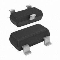
DIODE SW DBL 70V 215MA SOT23
Manufacturer
NXP Semiconductors
Datasheet
1.PMBD914235.pdf
(10 pages)
Specifications of PMBD914,215
Package / Case
SOT-23-3, TO-236-3, Micro3™, SSD3, SST3
Voltage - Forward (vf) (max) @ If
1.25V @ 150mA
Voltage - Dc Reverse (vr) (max)
100V
Current - Average Rectified (io)
215mA (DC)
Current - Reverse Leakage @ Vr
1µA @ 75V
Diode Type
Standard
Speed
Fast Recovery =< 500ns, > 200mA (Io)
Reverse Recovery Time (trr)
4ns
Capacitance @ Vr, F
1.5pF @ 0V, 1MHz
Mounting Type
Surface Mount
Product
Ultra Fast Recovery Rectifier
Configuration
Single
Reverse Voltage
100 V
Forward Voltage Drop
1.25 V at 0.15 A
Recovery Time
4 ns
Forward Continuous Current
0.215 A
Max Surge Current
4 A
Reverse Current Ir
0.025 uA
Mounting Style
SMD/SMT
Maximum Operating Temperature
+ 150 C
Minimum Operating Temperature
- 65 C
Lead Free Status / RoHS Status
Lead free / RoHS Compliant
Lead Free Status / RoHS Status
Lead free / RoHS Compliant, Lead free / RoHS Compliant
Other names
568-1737-2
933856870215
PMBD914 T/R
933856870215
PMBD914 T/R
Available stocks
Company
Part Number
Manufacturer
Quantity
Price

Part Number:
PMBD914,215
Manufacturer:
NXP/恩智浦
Quantity:
20 000


NXP Semiconductors
6. Thermal characteristics
7. Characteristics
PMBD914_6
Product data sheet
Table 6.
In accordance with the Absolute Maximum Rating System (IEC 60134).
[1]
[2]
[3]
Table 7.
[1]
[2]
Table 8.
T
[1]
[2]
Symbol
P
T
T
Symbol
R
R
Symbol
V
I
C
t
V
R
rr
amb
j
stg
tot
F
FR
th(j-a)
th(j-t)
d
Device mounted on an FR4 PCB, single-sided copper, tin-plated and standard footprint.
T
Soldering point of cathode tab.
Device mounted on an FR4 PCB, single-sided copper, tin-plated and standard footprint.
Soldering point of cathode tab.
When switched from I
When switched from I
= 25 C unless otherwise specified.
j
= 25 C prior to surge.
Parameter
forward voltage
reverse current
diode capacitance
reverse recovery time
forward recovery voltage
Limiting values
Thermal characteristics
Characteristics
Parameter
total power dissipation
junction temperature
storage temperature
Parameter
thermal resistance from
junction to ambient
thermal resistance from
junction to tie-point
F
F
Rev. 06 — 11 February 2009
= 10 mA to I
= 10 mA; t
…continued
r
= 20 ns.
R
= 10 mA; R
Conditions
I
I
I
I
V
V
V
V
f = 1 MHz; V
F
F
F
F
R
R
R
R
= 1 mA
= 10 mA
= 50 mA
= 150 mA
= 25 V
= 75 V
= 25 V; T
= 75 V; T
Conditions
T
Conditions
in free air
amb
L
= 100 ; measured at I
j
j
R
25 C
= 150 C
= 150 C
= 0 V
Single high-speed switching diode
[1][3]
[1]
[2]
[1]
[2]
Min
-
-
Min
-
-
Min
-
-
-
-
-
-
-
-
-
-
-
R
65
= 1 mA.
PMBD914
Typ
-
-
Typ
-
-
-
-
-
-
-
-
-
-
-
© NXP B.V. 2009. All rights reserved.
Max
250
150
+150
Max
500
330
Max
715
855
1
1.25
25
1
30
50
1.5
4
1.75
Unit
mW
C
C
Unit
K/W
K/W
Unit
mV
mV
V
V
nA
pF
ns
V
3 of 10
A
A
A
Related parts for PMBD914,215
Image
Part Number
Description
Manufacturer
Datasheet
Request
R

Part Number:
Description:
Single high-speed switching diode, fabricated in planar technology, and encapsulated in asmall Surface-Mounted Device (SMD) plastic package
Manufacturer:
NXP Semiconductors
Datasheet:

Part Number:
Description:
DIODE HIGH SPEED SWITCHING SOT23
Manufacturer:
NXP Semiconductors
Datasheet:

Part Number:
Description:
Single high-speed switching diode
Manufacturer:
NXP [NXP Semiconductors]
Datasheet:

Part Number:
Description:
NXP Semiconductors designed the LPC2420/2460 microcontroller around a 16-bit/32-bitARM7TDMI-S CPU core with real-time debug interfaces that include both JTAG andembedded trace
Manufacturer:
NXP Semiconductors
Datasheet:

Part Number:
Description:
NXP Semiconductors designed the LPC2458 microcontroller around a 16-bit/32-bitARM7TDMI-S CPU core with real-time debug interfaces that include both JTAG andembedded trace
Manufacturer:
NXP Semiconductors
Datasheet:
Part Number:
Description:
NXP Semiconductors designed the LPC2468 microcontroller around a 16-bit/32-bitARM7TDMI-S CPU core with real-time debug interfaces that include both JTAG andembedded trace
Manufacturer:
NXP Semiconductors
Datasheet:
Part Number:
Description:
NXP Semiconductors designed the LPC2470 microcontroller, powered by theARM7TDMI-S core, to be a highly integrated microcontroller for a wide range ofapplications that require advanced communications and high quality graphic displays
Manufacturer:
NXP Semiconductors
Datasheet:
Part Number:
Description:
NXP Semiconductors designed the LPC2478 microcontroller, powered by theARM7TDMI-S core, to be a highly integrated microcontroller for a wide range ofapplications that require advanced communications and high quality graphic displays
Manufacturer:
NXP Semiconductors
Datasheet:
Part Number:
Description:
The Philips Semiconductors XA (eXtended Architecture) family of 16-bit single-chip microcontrollers is powerful enough to easily handle the requirements of high performance embedded applications, yet inexpensive enough to compete in the market for hi
Manufacturer:
NXP Semiconductors
Datasheet:
Part Number:
Description:
The XA-S3 device is a member of Philips Semiconductors? XA(eXtended Architecture) family of high performance 16-bitsingle-chip microcontrollers
Manufacturer:
NXP Semiconductors
Datasheet:

Part Number:
Description:
The NXP BlueStreak LH75401/LH75411 family consists of two low-cost 16/32-bit System-on-Chip (SoC) devices
Manufacturer:
NXP Semiconductors
Datasheet:
Part Number:
Description:
The NXP LPC3130/3131 combine an 180 MHz ARM926EJ-S CPU core, high-speed USB2
Manufacturer:
NXP Semiconductors
Datasheet:
Part Number:
Description:
The NXP LPC3141 combine a 270 MHz ARM926EJ-S CPU core, High-speed USB 2
Manufacturer:
NXP Semiconductors
Part Number:
Description:
The NXP LPC3143 combine a 270 MHz ARM926EJ-S CPU core, High-speed USB 2
Manufacturer:
NXP Semiconductors