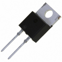
MUR8100EG ON Semiconductor, MUR8100EG Datasheet - Page 4

MUR8100EG
Manufacturer Part Number
MUR8100EG
Description
DIODE ULT FAST 8A 1000V TO220AC
Manufacturer
ON Semiconductor
Series
SWITCHMODE™r
Specifications of MUR8100EG
Voltage - Forward (vf) (max) @ If
1.8V @ 8A
Voltage - Dc Reverse (vr) (max)
1000V (1kV)
Current - Average Rectified (io)
8A
Current - Reverse Leakage @ Vr
25µA @ 1000V
Diode Type
Standard
Speed
Fast Recovery =< 500ns, > 200mA (Io)
Reverse Recovery Time (trr)
100ns
Mounting Type
Through Hole
Package / Case
TO-220-2, TO-220AC
Product
Ultra Fast Recovery Rectifier
Configuration
Single
Reverse Voltage
1000 V
Forward Voltage Drop
1.8 V
Recovery Time
100 ns
Forward Continuous Current
16 A
Max Surge Current
100 A
Reverse Current Ir
25 uA
Mounting Style
Through Hole
Maximum Operating Temperature
+ 175 C
Minimum Operating Temperature
- 65 C
Current, Forward
8 A
Current, Reverse
500 μA
Current, Surge
100 A
Package Type
TO-220
Primary Type
Rectifier
Resistance, Thermal, Junction To Case
2 °C/W
Speed, Switching
Ultrafast
Temperature, Junction, Maximum
+175 °C
Temperature, Operating
-65 to +175 °C
Time, Recovery
100 ns
Voltage, Forward
1.8 V
Voltage, Reverse
1000 V
Lead Free Status / RoHS Status
Lead free / RoHS Compliant
Capacitance @ Vr, F
-
Lead Free Status / Rohs Status
Lead free / RoHS Compliant
Other names
MUR8100EGOS
Available stocks
Company
Part Number
Manufacturer
Quantity
Price
Part Number:
MUR8100EG
Manufacturer:
ON/安森美
Quantity:
20 000
Figure 6 was used to demonstrate the controlled avalanche
capability of the new “E’’ series Ultrafast rectifiers. A
mercury switch was used instead of an electronic switch to
simulate a noisy environment when the switch was being
opened.
up linearly; and energy is stored in the coil. At t
is opened and the voltage across the diode under test begins
to rise rapidly, due to di/dt effects, when this induced voltage
reaches the breakdown voltage of the diode, it is clamped at
BV
which now starts to decay linearly through the diode, and
goes to zero at t
is opened; and calculating the energy that is transferred to
the diode it can be shown that the total energy transferred is
equal to the energy stored in the inductor plus a finite amount
of energy from the V
The unclamped inductive switching circuit shown in
When S
By solving the loop equation at the point in time when S
DUT
MERCURY
W
W
EQUATION (1):
EQUATION (2):
SWITCH
and the diode begins to conduct the full load current
AVAL
AVAL
1
is closed at t
S
[ 1
[ 1
1
2
.
2
2
Figure 6. Test Circuit
LI
LI
DD
2
LPK
2
LPK
0
power supply while the diode is in
the current in the inductor I
I
L
BV
BV
DUT
+V
40 mH COIL
DUT
DD
DUT
I
D
V
DD
1
the switch
CH1
CH2
V
L
http://onsemi.com
D
CH1
ramps
Figure 8. Current−Voltage Waveforms
500V
1
50mV
1
4
SAVEREF SOURCE
CH2
ACQUISITIONS
breakdown (from t
component resistances. Assuming the component resistive
elements are small Equation (1) approximates the total
energy transferred to the diode. It can be seen from this
equation that if the V
breakdown voltage of the device, the amount of energy
contributed by the supply during breakdown is small and the
total energy can be assumed to be nearly equal to the energy
stored in the coil during the time when S
Equation (2).
MUR8100E in this test circuit conducting a peak current of
one ampere at a breakdown voltage of 1300 V, and using
Equation (2) the energy absorbed by the MUR8100E is
approximately 20 mjoules.
condition, the new “E’’ series provides added protection
against those unforeseen transient viruses that can produce
unexplained random failures in unfriendly environments.
The oscilloscope picture in Figure 8, shows the
Although it is not recommended to design for this
t
0
Figure 7. Current−Voltage Waveforms
A
20ms
I
L
REF
1
953 V
to t
217:33 HRS
DD
2
) minus any losses due to finite
voltage is low compared to the
STACK
VERT
REF
t
1
BV
I
DUT
D
CHANNEL 2:
I
0.5 AMPS/DIV.
CHANNEL 1:
V
500 VOLTS/DIV.
TIME BASE:
20 ms/DIV.
L
DUT
t
1
2
was closed,
V
DD
t


