D4N-1132 Omron, D4N-1132 Datasheet - Page 10
D4N-1132
Manufacturer Part Number
D4N-1132
Description
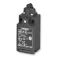
Switch
Manufacturer
Omron
Series
D4Nr
Type
Snap Action Safety Limitr
Specifications of D4N-1132
Operating Force Max
6.5N
Contact Voltage Ac Max
240V
Contact Voltage Dc Max
250V
Contact Current Ac Max
10A
Contact Current Dc Max
2.5A
Switch Terminals
Screw
Svhc
No SVHC (15-Dec-2010)
Contact Form
1 NC / 1 NO
Contact Rating
10 Amps at 120 VoltsAC, 240 VoltsAC
Actuator
Roller Plunger
Operating Force
6.5 N
Termination Style
Conduit
Ingress Protection
IP67
Lead Free Status / RoHS Status
Lead free / RoHS Compliant
Lead Free Status / RoHS Status
Lead free / RoHS Compliant


Dimensions
■ Switches
Note: All units are in millimeters unless otherwise indicated.
1-conduit Models
Note: 1. Unless otherwise specified, a tolerance of ±0.4 mm applies to all dimensions.
Snap-action (1NC/1NO) (2NC), Slow-action
(2NC) (3NC)
Note: 1. Variation occurs in the simultaneity of contact opening/closing oper-
10
Roller Lever (Resin Lever, Resin Roller)
D4N-1@20
D4N-3@20
D4N-9@20 (See note 2.)
Roller Lever (Metal Lever, Metal Roller)
D4N-1@25
D4N-3@25
D4N-9@25 (See note 2.)
OF max.
RF min.
PT
OT min.
MD max.
(See note 2.)
OP
TT
(See note 3.)
DOT min.
(See note 4.)
DOF min.
(See note 4.)
Model
2. Refer to page 13 for details on M12 connectors.
2. Only for snap-action models.
3. Reference value.
4.
ations of 2NC, 2NC/1NO, and 3NC contacts. Check contact opera-
tion.
!
that the minimum values or greater are provided.
Only for slow-action models. For safe use, always make sure
18
55
Miniature Safety Limit Switch
18
55
5.0 N
0.5 N
18° to 27°
40°
14°
---
(80° )
50°
20 N
Resin lever
47
9
47±
9±
±0.2
Metal lever
D4N-@120
D4N-@220
D4N-@B20
D4N-@D20
± 0.2
D4N-2@20
D4N-4@20
D4N-2@25
D4N-4@25
0.2
0.2
2.5
2.5
31 max.
31 max.
20
22
22
20±
22±
22±
± 0.1
± 0.1
± 0.2
17.5 dia. × 7
sintered stainless
steel roller
17.5 dia. × 6.8
resin roller
0.1
0.1
0.2
D4N-@B22
D4N-@D22
D4N-@122
D4N-@222
2.15±0.05R
mounting holes
Conduit cap
26R
2.15±0.05R
mounting holes
26R
Conduit cap
D4N-@B25
D4N-@D25
D4N-@125
D4N-@225
47
40
45 ±
39.5 ±
±1
±1
(27)
30
11
(31)
21.5
11 ±
1
30
21.5
14.2
±0.2
14.2
1
0.2
D4N
Two, 4
Depth: 5
20.5 × 20.5
27.5
Two, 4
Depth: 5
20.5 × 20.5
27.5
D4N-@B26
D4N-@D26
D4N-@126
D4N-@226
+0.15
0
+0.15
0
dia. holes
dia. holes
Slow-action (1NC/1NO) (2NC/1NO)
Note: 1. These PT values are possible when the NC contacts are open
Roller Lever (Metal Lever, Resin Roller)
D4N-1@22
D4N-3@22
D4N-9@22 (See note 2.)
Roller Lever (Metal Lever, Bearing Roller)
D4N-1@26
D4N-3@26
D4N-9@26 (See note 2.)
OF max.
RF min.
PT
(See note 1.)
PT (2nd)
(See note 2.)
PT (See note 3.)
PT (2nd)
(See note 4.)
OT min.
OP
TT (See note 5.)
DOT min. (See note 6.) 50°
DOF min. (See note 6.) 20 N
2. These PT values are possible when the NO contacts are closed
3. Only for MBB models.
4. Reference values for MBB models only.
5. Reference values.
6.
Model
!
(OFF).
(ON).
18
55
18
55
For safe use, always make sure that the minimum values or
greater are provided.
47±
9±
Metal lever
47±
9±
0.2
Metal lever
0.2
0.2
0.2
D4N-2@22
D4N-4@22
D4N-2@26
D4N-4@26
2.5
5.0 N
0.5 N
18° to 27°
(44° )
27.5° to 36.5°
(18° )
40°
---
(80° )
2.5
D4N-@A20
D4N-@C20
D4N-@E20
D4N-@F20
31 max.
20±
22±
22±
31 max.
20±
22±
22±
0.1
0.1
0.2
17.5 dia. × 6.8
resin roller
17 dia. × 6
Bearing roller
0.1
0.1
0.2
2.15±0.05R
mounting holes
Conduit cap
26R
2.15±0.05R
mounting holes
26R
Conduit cap
D4N-@A22
D4N-@C22
D4N-@E22
D4N-@F22
45 ±
39.5 ±
43.6 ±
39 ±
D4N-@A25
D4N-@C25
D4N-@E25
D4N-@F25
(31)
(31.5)
11 ±
30
1
21.5
11 ±
30
14.2
21.5
1
1
1
14.2
0.2
0.2
20.5 × 20.5
Two, 4
Depth: 5
27.5
20.5 × 20.5
Two, 4
Depth: 5
27.5
+0.15
0
D4N-@A26
D4N-@C26
D4N-@E26
D4N-@F26
+0.15
0
dia. holes
dia. holes
Related parts for D4N-1132
Image
Part Number
Description
Manufacturer
Datasheet
Request
R

Part Number:
Description:
LIMIT SWITCH, ROLLER LEVER
Manufacturer:
Omron
Datasheet:

Part Number:
Description:
PlasLS/Jap/Snp1NC1NO/RlrLvr
Manufacturer:
Omron
Datasheet:

Part Number:
Description:
NPT,1NC1NO Snap,TopRlrPlng
Manufacturer:
Omron
Datasheet:
Part Number:
Description:
D4N-3C2G, 2NC+1NO, Adj Roller Lever, Slow Act, 1/2 In. NPT
Manufacturer:
Omron
Part Number:
Description:
D4N-3B2G, 2NC, Adj Roller Lever, Slow Act, 1/2 In. NPT
Manufacturer:
Omron
Datasheet:
Part Number:
Description:
D4N-3B2H, 2NC, Adj Roller Lever Rubber, Slow Act, 1/2 In. NPT
Manufacturer:
Omron
Datasheet:

Part Number:
Description:
SafetySwitch/1NC
Manufacturer:
Omron
Datasheet:

Part Number:
Description:
PlasLS/PG13.5/Snp1NC1NO/AdjRlr
Manufacturer:
Omron
Datasheet:

Part Number:
Description:
PlasLS/NPT/Snp1NC1NO/AdjRlr
Manufacturer:
Omron
Datasheet:
Part Number:
Description:
1/2-14NPT,1NC/1NO,Snp,rol
Manufacturer:
Omron
Datasheet:
Part Number:
Description:
Safety Limit Switch
Manufacturer:
Omron
Datasheet:
Part Number:
Description:
Limit Switch
Manufacturer:
Omron
Datasheet:
Part Number:
Description:
D4N-3B2G, 2NC, Adj Roller Lever, Slow Act, 1/2 In. NPT
Manufacturer:
Omron
Datasheet:
Part Number:
Description:
D4N-3B2H, 2NC, Adj Roller Lever Rubber, Slow Act, 1/2 In. NPT
Manufacturer:
Omron
Datasheet:
Part Number:
Description:
D4N-4122, 1NC+1NO, Roller Lever, Snap Act, M20
Manufacturer:
Omron
Datasheet: