D4N-1132 Omron, D4N-1132 Datasheet - Page 20
D4N-1132
Manufacturer Part Number
D4N-1132
Description
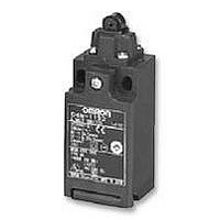
Switch
Manufacturer
Omron
Series
D4Nr
Type
Snap Action Safety Limitr
Specifications of D4N-1132
Operating Force Max
6.5N
Contact Voltage Ac Max
240V
Contact Voltage Dc Max
250V
Contact Current Ac Max
10A
Contact Current Dc Max
2.5A
Switch Terminals
Screw
Svhc
No SVHC (15-Dec-2010)
Contact Form
1 NC / 1 NO
Contact Rating
10 Amps at 120 VoltsAC, 240 VoltsAC
Actuator
Roller Plunger
Operating Force
6.5 N
Termination Style
Conduit
Ingress Protection
IP67
Lead Free Status / RoHS Status
Lead free / RoHS Compliant
Lead Free Status / RoHS Status
Lead free / RoHS Compliant


Two-conduit Type
• Make sure that the dog contacts the actuator at a right angle.
Wiring
• When connecting to the terminals via insulating tube and M3.5
One-conduit Type (3 Poles)
Two-conduit Type (3 Poles)
• Do not push crimp terminals into gaps in the case interior. Doing so
• Use crimp terminals not more than 0.5 mm in thickness. Otherwise,
20
A
C
E
J.S.T.
Applying a load to the switch actuator (roller) on a slant may result
in deformation or damage of the actuator or rotary shaft.
crimp terminals, arrange the crimp terminals as shown below so
that they do not rise up onto the case or the cover. Applicable lead
wire size: AWG20 to AWG18 (0.5 to 0.75 mm
Use lead wires of an appropriate length, as shown below. Not doing
so may result in excess length causing the cover to rise and not fit
properly.
may cause damage or deformation of the case.
they will interfere with other components inside the case. The crimp
terminals shown below are not more than 0.5 mm thick.
Manufacture
J.S.T is a Japanese manufacturer.
11
21
33
12
22
34
A
C
E
5.35
Miniature Safety Limit Switch
B
D
F
±0.1
11
21
33
42 mm
2.5
39
12
22
34
±0.1
±0.1
FV0.5-3.7 (F type)
V0.5-3.7 (straight type)
Left hand
E
Two, M4
C
B
D
F
A
B D F
Type
20
22
40
42
42
Tolerance ±2 mm
±0.1
±0.1
±0.1
±0.1
±0.1
28 mm
E
C
Dog
A
B
D
28 mm
4
Height: 4.8 max.
F
−0.05
−0.15
AWG20 (0.5 mm
Tolerance ±2 mm
28 mm
dia.
2
Right hand
).
E
33 mm
C
Wire size
A
D4N
B D F
42 mm
Tolerance ±2 mm
42 mm
2
)
Contact Arrangement
• The following diagrams show the contact arrangements used for
Screw Terminal Type
Connector Type
• Applicable socket: XS2F (OMRON).
• Refer to the G010 Connector Catalog for details on socket pin num-
Socket Tightening (Connector Type)
• Turn the socket connector screws by hand and tighten until no
• Make sure that the socket connector is tightened securely. Other-
Conduit Opening
• Connect a recommended connector to the opening of the conduit
• When using 1/2-14NPT, wind sealing tape around the joint between
D4N-@D@@ (3NC)
D4N-@B@@ (2NC)
D4N-@2@@ (2NC (SNAP))
D4N-9B@@ (2NC)
D4N-92@@ (2NC (SNAP))
screw terminal types and connector types.
bers and lead wire colors.
space remains between the socket and the plug.
wise, the rated degree of protection (IP67) may not be maintained
and vibration may loosen the socket connector.
and tighten the connector to the specified torque. The case may be
damaged if an excessive tightening torque is applied.
the connector and conduit opening so that the enclosure will con-
form to IP67.
(1) 11
(3) 31
Pin No. (Terminal No.)
11
21
31
11
31
2
dz dia.: 3.7 mm
D dia.: 2.9 mm
1
3
Crimp terminal
B: 6.6 mm
F: 7.7 mm
L: 19 mm
I:
t: 0.5 mm
4
8.0 mm
12 (2)
32 (4)
12
22
32
12
32
Correct
D
D4N-9A@@ (1NC/1NO)
D4N-9E@@ (1NC/1NO (MBB))
D4N-91@@ (1NC/1NO (SNAP))
D4N-@C@@ (2NC/1NO)
D4N-@F@@ (2NC/1NO (MBB))
D4N-@A@@ (1NC/1NO)
D4N-@E@@ (1NC/1NO (MBB))
D4N-@1@@ (1NC/1NO (SNAP))
l
(3) 13
(1) 31
(1) 11
(3) 33
13
31
11
21
33
11
33
L
Incorrect
F
dz
Terminal screw
12 (2)
34 (4)
14 (4)
32 (2)
12
22
34
12
34
14
32
B
Related parts for D4N-1132
Image
Part Number
Description
Manufacturer
Datasheet
Request
R

Part Number:
Description:
LIMIT SWITCH, ROLLER LEVER
Manufacturer:
Omron
Datasheet:

Part Number:
Description:
PlasLS/Jap/Snp1NC1NO/RlrLvr
Manufacturer:
Omron
Datasheet:

Part Number:
Description:
NPT,1NC1NO Snap,TopRlrPlng
Manufacturer:
Omron
Datasheet:
Part Number:
Description:
D4N-3C2G, 2NC+1NO, Adj Roller Lever, Slow Act, 1/2 In. NPT
Manufacturer:
Omron
Part Number:
Description:
D4N-3B2G, 2NC, Adj Roller Lever, Slow Act, 1/2 In. NPT
Manufacturer:
Omron
Datasheet:
Part Number:
Description:
D4N-3B2H, 2NC, Adj Roller Lever Rubber, Slow Act, 1/2 In. NPT
Manufacturer:
Omron
Datasheet:

Part Number:
Description:
SafetySwitch/1NC
Manufacturer:
Omron
Datasheet:

Part Number:
Description:
PlasLS/PG13.5/Snp1NC1NO/AdjRlr
Manufacturer:
Omron
Datasheet:

Part Number:
Description:
PlasLS/NPT/Snp1NC1NO/AdjRlr
Manufacturer:
Omron
Datasheet:
Part Number:
Description:
1/2-14NPT,1NC/1NO,Snp,rol
Manufacturer:
Omron
Datasheet:
Part Number:
Description:
Safety Limit Switch
Manufacturer:
Omron
Datasheet:
Part Number:
Description:
Limit Switch
Manufacturer:
Omron
Datasheet:
Part Number:
Description:
D4N-3B2G, 2NC, Adj Roller Lever, Slow Act, 1/2 In. NPT
Manufacturer:
Omron
Datasheet:
Part Number:
Description:
D4N-3B2H, 2NC, Adj Roller Lever Rubber, Slow Act, 1/2 In. NPT
Manufacturer:
Omron
Datasheet:
Part Number:
Description:
D4N-4122, 1NC+1NO, Roller Lever, Snap Act, M20
Manufacturer:
Omron
Datasheet: