MBRS330T3 ON Semiconductor, MBRS330T3 Datasheet

DIODE SCHOTTKY 30V 4A SMC

MBRS330T3

Manufacturer Part Number
MBRS330T3
Description
DIODE SCHOTTKY 30V 4A SMC
Manufacturer
ON Semiconductor
Datasheet

Specifications of MBRS330T3

Voltage - Forward (vf) (max) @ If
500mV @ 3A
Voltage - Dc Reverse (vr) (max)
30V
Current - Average Rectified (io)
4A
Current - Reverse Leakage @ Vr
2mA @ 30V
Diode Type
Schottky
Speed
Fast Recovery =< 500ns, > 200mA (Io)
Mounting Type
Surface Mount
Package / Case
DO-214AB, SMC
Lead Free Status / RoHS Status
Contains lead / RoHS non-compliant
Reverse Recovery Time (trr)
-
Capacitance @ Vr, F
-
Other names
MBRS330T3OSTR

Available stocks

Company
Part Number
Manufacturer
Quantity
Price
Part Number:
MBRS330T3
Manufacturer:
ON
Quantity:
2 230
Part Number:
MBRS330T3
Manufacturer:
AMOTECH
Quantity:
10 122
Part Number:
MBRS330T3
Manufacturer:
ON/安森美
Quantity:
20 000
Part Number:
MBRS330T3G
Manufacturer:
ONS
Quantity:
12 000
Part Number:
MBRS330T3G
Manufacturer:
ON Semiconductor
Quantity:
4 650
Part Number:
MBRS330T3G
0
Company:
Part Number:
MBRS330T3G
Quantity:
5 000
MBRS320T3, MBRS330T3,
MBRS340T3
Surface Mount
Schottky Power Rectifier
metal−to−silicon power diode. State−of−the−art geometry features
epitaxial construction with oxide passivation and metal overlay
contact. Ideally suited for low voltage, high frequency rectification, or
as free wheeling and polarity protection diodes, in surface mount
applications where compact size and weight are critical to the system.
Features
Mechanical Characteristics
© Semiconductor Components Industries, LLC, 2008
November, 2008 − Rev. 9
These devices employ the Schottky Barrier principle in a large area
(0.5 V Max @ 3.0 A, T
Leads are Readily Solderable
260°C Max. for 10 Seconds
Small Compact Surface Mountable Package with J−Bend Leads
Rectangular Package for Automated Handling
Highly Stable Oxide Passivated Junction
Very Low Forward Voltage Drop
Excellent Ability to Withstand Reverse Avalanche Energy Transients
Guard−Ring for Stress Protection
Device Passes ISO 7637 Pulse #1
Pb−Free Packages are Available
Case: Epoxy, Molded, Epoxy Meets UL 94 V−0
Weight: 217 mg (Approximately)
Finish: All External Surfaces Corrosion Resistant and Terminal
Lead and Mounting Surface Temperature for Soldering Purposes:
Polarity: Notch in Plastic Body Indicates Cathode Lead
Device Meets MSL 1 Requirements
ESD Ratings: Machine Model, C > 400 V
Human Body Model, 3B > 8000 V
J
= 25°C)
1
†For information on tape and reel specifications,
MBRS320T3
MBRS320T3G
MBRS330T3
MBRS330T3G
MBRS340T3
MBRS340T3G
including part orientation and tape sizes, please
refer to our Tape and Reel Packaging Specification
Brochure, BRD8011/D.
Device
SCHOTTKY BARRIER
ORDERING INFORMATION
B3x
x
A
Y
WW
G
(Note: Microdot may be in either location)
20, 30, 40 VOLTS
MARKING DIAGRAM
3.0 AMPERES
http://onsemi.com
RECTIFIERS
= Device Code
= 2, 3 or 4
= Assembly Location
= Year
= Work Week
= Pb−Free Package
(Pb−Free)
(Pb−Free)
(Pb−Free)
Package
SMC
SMC
SMC
SMC
SMC
SMC
AYWW
B3xG
Publication Order Number:
G
CASE 403
PLASTIC
2500/Tape & Reel
2500/Tape & Reel
2500/Tape & Reel
2500/Tape & Reel
2500/Tape & Reel
2500/Tape & Reel
SMC
MBRS340T3/D
Shipping

Related parts for MBRS330T3

MBRS330T3 Summary of contents

Page 1

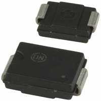
... MBRS320T3, MBRS330T3, MBRS340T3 Surface Mount Schottky Power Rectifier These devices employ the Schottky Barrier principle in a large area metal−to−silicon power diode. State−of−the−art geometry features epitaxial construction with oxide passivation and metal overlay contact. Ideally suited for low voltage, high frequency rectification free wheeling and polarity protection diodes, in surface mount applications where compact size and weight are critical to the system ...

Page 2

... FSM qJL 125°C J 0.1 0.7 0.8 0.9 1.0 0.0 0 MAXIMUM INSTANTANEOUS FORWARD VOLTAGE (V) F Figure 2. Maximum Forward Voltage http://onsemi.com 2 MBRS330T3 MBRS340T3 110° 105° − +150 5000 Pulses >400 >8000 11 0.50 2 100° 25° −65° ...

Page 3

TYPICAL ELECTRICAL CHARACTERISTICS 1.E−01 1.E− 125°C J 1.E− 100°C J 1.E−04 1.E− 25°C J 1.E− REVERSE VOLTAGE (V) R Figure 3. Typical Reverse Current 5 4.5 dc ...

Page 4

... Pb−Free strategy and soldering details, please download the ON Semiconductor Soldering and Mounting Techniques Reference Manual, SOLDERRM/D. ON Semiconductor and are registered trademarks of Semiconductor Components Industries, LLC (SCILLC). SCILLC reserves the right to make changes without further notice to any products herein ...

Related keywords