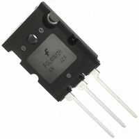
FGL40N120ANTU Fairchild Semiconductor, FGL40N120ANTU Datasheet - Page 5

FGL40N120ANTU
Manufacturer Part Number
FGL40N120ANTU
Description
IGBT NPT 1200V 64A TO-264
Manufacturer
Fairchild Semiconductor
Datasheet
1.FGL40N120ANTU.pdf
(7 pages)
Specifications of FGL40N120ANTU
Igbt Type
NPT
Voltage - Collector Emitter Breakdown (max)
1200V
Vce(on) (max) @ Vge, Ic
3.2V @ 15V, 40A
Current - Collector (ic) (max)
64A
Power - Max
500W
Input Type
Standard
Mounting Type
Through Hole
Package / Case
TO-264
Rohs Compliant
YES
Lead Free Status / RoHS Status
Lead free / RoHS Compliant
FGL40N120AN Rev. A1
Typical Performance Characteristics
Figure 13. Switching Loss vs. Collector Current
Figure 15. SOA Characteristics
0.01
100
0.1
0.1
10
10
1
1
0.1
Common Emitter
V
T
T
Single Nonrepetitive
Pulse Tc = 25
Curves must be derated
linearly with increase
in temperature
Ic MAX (Continuous)
20
Ic MAX (Pulsed)
C
C
GE
= 25
= 125
=
±
15V, R
°
C
°
C
30
Collector - Emitter Voltage, V
1
G
o
C
= 5
Collector Current, I
1E-3
0.01
0.1
Ω
40
1
1E-5
10
0.02
0.5
0.2
0.01
DC Operation
0.05
0.1
50
60
C
single pulse
[A]
1E-4
100
1ms
CE
Figure 17. Transient Thermal Impedance of IGBT
70
[V]
100
Eon
Eoff
µ
s
1000
80
50
µ
1E-3
s
Rectangular Pulse Duration [sec]
(Continued)
5
0.01
Figure 14. Gate Charge Characteristics
Figure 16. Turn-Off SOA
100
16
14
12
10
10
8
6
4
2
0
1
0
1
Common Emitter
R
T
0.1
C
L
= 15
= 25
Ω
°
C
50
Collector-Emitter Voltage, V
Pdm
Pdm
Duty factor D = t1 / t2
Peak Tj = Pdm × Zthjc + T
10
Duty factor D = t1 / t2
Peak Tj = Pdm × Zthjc + T
Gate Charge, Q
Safe Operating Area
V
1
GE
100
t1
t1
= 15V, T
t2
t2
Vcc = 200V
C
= 125
150
100
g
C
[nC]
C
10
o
C
CE
400V
[V]
200
600V
www.fairchildsemi.com
1000
250


