IXBH42N170 IXYS, IXBH42N170 Datasheet - Page 5
IXBH42N170
Manufacturer Part Number
IXBH42N170
Description
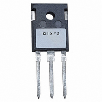
IGBT HIVOLT 1700V 75A TO-247
Manufacturer
IXYS
Series
BIMOSFET™r
Datasheet
1.IXBH42N170.pdf
(5 pages)
Specifications of IXBH42N170
Voltage - Collector Emitter Breakdown (max)
1700V
Vce(on) (max) @ Vge, Ic
2.8V @ 15V, 42A
Current - Collector (ic) (max)
80A
Power - Max
360W
Input Type
Standard
Mounting Type
Through Hole
Package / Case
TO-247AD
Configuration
Single
Collector- Emitter Voltage Vceo Max
1700 V
Maximum Gate Emitter Voltage
20 V
Power Dissipation
360 W
Maximum Operating Temperature
+ 150 C
Continuous Collector Current Ic Max
75 A
Minimum Operating Temperature
- 55 C
Mounting Style
Through Hole
Channel Type
N
Collector-emitter Voltage
1.7kV
Collector Current (dc) (max)
80A
Gate To Emitter Voltage (max)
±20V
Package Type
TO-247AD
Pin Count
3 +Tab
Mounting
Through Hole
Operating Temperature (min)
-55C
Operating Temperature (max)
150C
Operating Temperature Classification
Military
Vces, (v)
1700
Ic25, Tc=25°c, (a)
80
Ic90, Tc=90°c, (a)
42
Vce(sat), Typ, Tj=25°c, (v)
2.8
Tf Typ, Tj=25°c, (ns)
740
Gate Drive, (v)
15
Rthjc, Max, (k/w)
0.35
Package Style
TO-247
Lead Free Status / RoHS Status
Lead free / RoHS Compliant
Igbt Type
-
Lead Free Status / Rohs Status
Lead free / RoHS Compliant
Other names
Q1157068
Available stocks
Company
Part Number
Manufacturer
Quantity
Price
Company:

Part Number:
IXBH42N170
Manufacturer:
TOSHIBA
Quantity:
2 000
Company:
Part Number:
IXBH42N170A
Manufacturer:
IXYS
Quantity:
18 000


© 2008 IXYS CORPORATION, All rights reserved
1300
1200
1100
1000
360
320
280
240
200
160
120
800
700
600
500
400
300
200
100
900
800
700
600
500
400
300
80
25
10
20
Switching Times vs. Gate Resistance
25
R
V
V
Switching Times vs. Drain Current
GE
CE
G
t
T
V
35
15
r
J
CE
= 10Ω
Rise Time vs. Junction Temperature
= 125ºC, V
= 15V
= 850V
30
= 850V
Fig. 17. Resistive Turn-off
I
Fig. 15. Resistive Turn-on
45
C
20
35
= 84A
Fig. 13. Resistive Turn-on
T
40
t
d(on)
J
55
GE
25
T
= 25ºC, 125ºC
J
= 15V
45
- Degrees Centigrade
- - - -
I
C
R
65
30
- Amperes
50
G
- Ohms
I
I
55
C
75
t
R
V
C
35
I
= 42A
f
G
CE
= 84A
C
= 10Ω, V
60
= 42A
= 850V
85
40
65
t
GE
d(off)
70
95
45
= 15V
75
- - - -
105
50
80
115
85
55
440
420
400
380
360
340
320
300
280
260
240
160
140
120
100
80
60
40
20
125
1200
1100
1000
900
800
700
600
500
400
300
360
320
280
240
200
160
120
900
800
700
600
500
400
300
80
40
0
20
25
10
Switching Times vs. Junction Temperature
t
R
V
Switching Times vs. Gate Resistance
25
f
G
CE
R
V
V
35
15
GE
CE
G
= 10Ω, V
t
T
V
= 850V
f
J
CE
= 10Ω
= 15V
= 850V
= 125ºC, V
30
= 850V
45
Fig. 18. Resistive Turn-off
Fig. 16. Resistive Turn-off
20
Rise Time vs. Drain Current
35
Fig. 14. Resistive Turn-on
t
GE
d(off)
55
T
= 15V
25
J
t
40
d(off
GE
I
- Degrees Centigrade
- - - -
C
I
I
65
= 15V
= 42A
C
C
)
45
R
= 84A
- - - -
30
= 42A
G
I
C
- Ohms
75
50
- Amperes
T
35
T
J
J
= 125ºC
55
= 25ºC
85
40
60
95
45
65
IXBH42N170
I
IXBT42N170
105
C
= 84A
IXYS REF: B_42N170(7N)10-07-08
70
50
115
75
55
125
80
1800
1600
1400
1200
1000
800
600
400
200
0
380
360
340
320
300
280
260
85
Related parts for IXBH42N170
Image
Part Number
Description
Manufacturer
Datasheet
Request
R

Part Number:
Description:
TRANS IGBT CHIP N-CH 1400V 15A 3TO-247 AD
Manufacturer:
IXYS Corporation
Part Number:
Description:
High Voltage, High Gain BIMOSFETTM Monolithic Bipolar MOS Transistor
Manufacturer:
IXYS Corporation
Datasheet:
Part Number:
Description:
TRANS IGBT CHIP N-CH 1400V 20A 3TO-247 AD
Manufacturer:
IXYS Corporation
Part Number:
Description:
TRANS IGBT CHIP N-CH 1400V 33A 3TO-247 AD
Manufacturer:
IXYS Corporation
Part Number:
Description:
BIMOSFET Monolithic Bipolar MOS Transistor
Manufacturer:
IXYS Corporation
Part Number:
Description:
TRANS IGBT CHIP N-CH 1700V 75A 3TO-247 AD
Manufacturer:
IXYS Corporation
Part Number:
Description:
High Voltage, High Gain BIMOSFET Monolithic Bipolar MOS Transistor
Manufacturer:
IXYS Corporation
Part Number:
Description:
TRANS IGBT CHIP N-CH 1400V 9A 3TO-247 AD
Manufacturer:
IXYS Corporation
Part Number:
Description:
TRANS IGBT CHIP N-CH 1400V 9A 3TO-247 AD
Manufacturer:
IXYS Corporation

Part Number:
Description:
HiPerFET Power MOSFETs
Manufacturer:
IXYS Corporation
Datasheet: