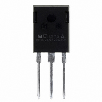
IXGR24N120C3D1 IXYS, IXGR24N120C3D1 Datasheet - Page 5

IXGR24N120C3D1
Manufacturer Part Number
IXGR24N120C3D1
Description
IGBT PT 1200V 48A DIO ISOPLUS247
Manufacturer
IXYS
Series
GenX3™r
Datasheet
1.IXGR24N120C3D1.pdf
(7 pages)
Specifications of IXGR24N120C3D1
Igbt Type
PT
Voltage - Collector Emitter Breakdown (max)
1200V
Vce(on) (max) @ Vge, Ic
4.2V @ 15V, 20A
Current - Collector (ic) (max)
48A
Power - Max
200W
Input Type
Standard
Mounting Type
Through Hole
Package / Case
ISOPLUS247™
Vces, (v)
1200
Ic25, Tc=25°c, Igbt, (a)
48
Ic90, Tc=90°c, Igbt, (a)
-
Ic110, Tc=110°c, Igbt, (a)
-
Vce(sat), Max, Tj=25°c, Igbt, (v)
4.2
Tfi, Typ, Tj=25°c, Igbt, (ns)
110
Eoff, Typ, Tj=125°c, Igbt, (mj)
1.18
Rthjc, Max, Igbt, (°c/w)
1
If, Tj=110°c, Diode, (a)
-
Rthjc, Max, Diode, (ºc/w)
-
Package Style
ISOPLUS 247
Lead Free Status / RoHS Status
Lead free / RoHS Compliant
© 2008 IXYS CORPORATION, All rights reserved
1.5
1.4
1.3
1.2
1.1
1.0
0.9
0.8
0.7
0.6
0.5
0.4
1.4
1.2
1.0
0.8
0.6
0.4
0.2
0.0
380
340
300
260
220
180
140
100
60
20
25
4
10
Energy Loss vs. Junction Temperature
Switching Times vs. Collector Current
t
R
V
E
R
V
35
E
T
V
f
11
G
CE
off
G
CE
J
off
CE
6
Energy Loss vs. Gate Resistance
= 5 Ω , V
= 5 Ω
= 125ºC , V
= 600V
= 600V
= 600V
Fig. 14. Inductive Switching
Fig. 12. Inductive Switching
45
12
Fig. 16. Inductive Turn-off
,
8
V
T
t
GE
GE
J
d(off
E
55
13
- Degrees Centigrade
on
E
= 15V
= 15V
GE
on
)
I
- - - -
- - - -
C
10
= 15V
R
- - - -
14
65
- Amperes
G
- Ohms
15
75
12
I
C
= 20A
16
85
I
14
C
T
= 10A
J
17
95
= 25ºC
T
J
I
I
16
C
= 125ºC
C
18
= 10A
105
= 20A
18
19
115
20
125
20
130
125
120
115
110
105
100
95
90
85
4.2
3.6
3.0
2.4
1.8
1.2
0.6
0.0
3.4
3.2
3.0
2.8
2.6
2.4
2.2
2.0
1.8
1.6
1.4
1.2
1.8
1.6
1.4
1.2
1.0
0.8
0.6
0.4
0.2
0.0
350
300
250
200
150
100
360
340
320
300
280
260
240
220
200
50
10
25
Switching Times vs. Junction Temperature
4
E
R
V
Switching Times vs. Gate Resistance
t
R
V
T
11
off
CE
G
t
T
V
f
35
CE
G
J
T
f
J
CE
Energy Loss vs. Collector Current
= 5 Ω
= 125ºC
J
6
= 5 Ω , V
= 600V
= 125ºC, V
= 600V
= 25ºC
= 600V
12
45
Fig. 13. Inductive Switching
Fig. 15. Inductive Turn-off
Fig. 17. Inductive Turn-off
,
I
C
I
T
V
8
t
= 20A
C
d(off)
J
GE
GE
E
13
55
t
= 20A
- Degrees Centigrade
d(off
on
GE
= 15V
= 15V
I
- - - -
- - - -
C
)
10
= 15V
R
- - - -
65
14
- Amperes
G
- Ohms
I
C
75
15
12
IXGR24N120C3D1
= 10A
85
16
14
I
C
= 10A
95
17
16
105
18
18
115
19
125
20
20
140
130
120
110
100
90
80
400
360
320
280
240
200
160
120
80
3.6
3.2
2.8
2.4
2.0
1.6
1.2
0.8
0.4
0.0


