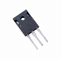
HGTG11N120CND Fairchild Semiconductor, HGTG11N120CND Datasheet - Page 3

HGTG11N120CND
Manufacturer Part Number
HGTG11N120CND
Description
IGBT NPT N-CH 1200V 43A TO-247
Manufacturer
Fairchild Semiconductor
Datasheet
1.HGTG11N120CND.pdf
(8 pages)
Specifications of HGTG11N120CND
Igbt Type
NPT
Voltage - Collector Emitter Breakdown (max)
1200V
Vce(on) (max) @ Vge, Ic
2.4V @ 15V, 11A
Current - Collector (ic) (max)
43A
Power - Max
298W
Input Type
Standard
Mounting Type
Through Hole
Package / Case
TO-247-3
Configuration
Single
Collector- Emitter Voltage Vceo Max
1200 V
Collector-emitter Saturation Voltage
2.1 V
Maximum Gate Emitter Voltage
+/- 20 V
Continuous Collector Current At 25 C
43 A
Gate-emitter Leakage Current
+/- 250 nA
Power Dissipation
298 W
Maximum Operating Temperature
+ 150 C
Continuous Collector Current Ic Max
43 A
Minimum Operating Temperature
- 55 C
Mounting Style
Through Hole
Transistor Type
IGBT
Dc Collector Current
43A
Collector Emitter Voltage Vces
2.4V
Power Dissipation Pd
298W
Collector Emitter Voltage V(br)ceo
1.2kV
Transistor Case Style
TO-247
No. Of Pins
3
Svhc
No SVHC
Rohs Compliant
Yes
Channel Type
N
Collector-emitter Voltage
1.2kV
Collector Current (dc) (max)
43A
Gate To Emitter Voltage (max)
±20V
Package Type
TO-247
Pin Count
3 +Tab
Mounting
Through Hole
Operating Temperature (min)
-55C
Operating Temperature (max)
150C
Operating Temperature Classification
Military
Operating Temperature Range
-55°C To +150°C
Lead Free Status / RoHS Status
Lead free / RoHS Compliant
Available stocks
Company
Part Number
Manufacturer
Quantity
Price
Company:
Part Number:
HGTG11N120CND
Manufacturer:
FSC
Quantity:
5 000
Part Number:
HGTG11N120CND
Manufacturer:
FAIRCHILD/ن»™ç«¥
Quantity:
20 000
©2001 Fairchild Semiconductor Corporation
Electrical Specifications
NOTE:
Typical Performance Curves
Current Turn-On Delay Time
Current Rise Time
Current Turn-Off Delay Time
Current Fall Time
Turn-On Energy
Turn-Off Energy (Note 3)
Diode Forward Voltage
Diode Reverse Recovery Time
Thermal Resistance Junction To Case
3. Turn-Off Energy Loss (E
FIGURE 1. DC COLLECTOR CURRENT vs CASE
45
40
35
30
25
20
15
10
at the point where the collector current equals zero (I
of Power Device Turn-Off Switching Loss. This test method produces the true total Turn-Off Energy Loss.
0
5
25
PARAMETER
TEMPERATURE
50
T
C
, CASE TEMPERATURE (
OFF
75
) is defined as the integral of the instantaneous power loss starting at the trailing edge of the input pulse and ending
T
C
= 25
100
o
C, Unless Otherwise Specified (Continued)
Unless Otherwise Specified
o
SYMBOL
C)
t
t
d(OFF)I
d(ON)I
E
R
E
V
OFF
t
t
t
θJC
ON
EC
125
rr
rI
fI
V
CE
GE
= 0A). All devices were tested per JEDEC Standard No. 24-1 Method for Measurement
= 15V
IGBT and Diode at T
I
V
V
R
L = 2mH,
Test Circuit (Figure 20)
I
I
I
IGBT
Diode
CE
EC
EC
EC
GE
CE
G
150
= 10 Ω ,
= 11A,
= 11A
= 11A, dl
= 1A, dl
= 960V,
= 15V,
TEST CONDITIONS
EC
EC
/dt = 200A/ µ s
/dt = 200A/ µ s
FIGURE 2. MINIMUM SWITCHING SAFE OPERATING AREA
60
50
40
30
20
10
0
J
0
= 150
T
J
o
= 150
C,
200
V
CE
o
, COLLECTOR TO EMITTER VOLTAGE (V)
C, R
400
G
= 10Ω, V
MIN
-
-
-
-
-
-
-
-
-
-
-
600
GE
= 15V, L = 400µH
TYP
210
360
800
1.9
2.1
2.6
21
12
60
32
-
-
1000
HGTG11N120CND Rev. B
MAX
0.42
1.25
280
400
2.5
2.5
3.2
24
16
70
40
1200
UNITS
o
o
C/W
C/W
mJ
mJ
ns
ns
ns
ns
ns
ns
V
1400


