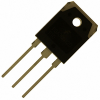
FGA30N120FTDTU Fairchild Semiconductor, FGA30N120FTDTU Datasheet - Page 6

FGA30N120FTDTU
Manufacturer Part Number
FGA30N120FTDTU
Description
IGBT 30A 1200V TRENCH TO-3P
Manufacturer
Fairchild Semiconductor
Datasheet
1.FGA30N120FTDTU.pdf
(9 pages)
Specifications of FGA30N120FTDTU
Igbt Type
Trench and Field Stop
Voltage - Collector Emitter Breakdown (max)
1200V
Vce(on) (max) @ Vge, Ic
2V @ 15V, 30A
Current - Collector (ic) (max)
60A
Power - Max
339W
Input Type
Standard
Mounting Type
Through Hole
Package / Case
TO-3P
Channel Type
N
Configuration
Single
Collector-emitter Voltage
1.2kV
Collector Current (dc) (max)
60A
Gate To Emitter Voltage (max)
±25V
Package Type
TO-3PN
Pin Count
3 +Tab
Mounting
Through Hole
Operating Temperature (max)
150C
Operating Temperature Classification
Military
Collector- Emitter Voltage Vceo Max
1200 V
Collector-emitter Saturation Voltage
2 V
Maximum Gate Emitter Voltage
+/- 25 V
Continuous Collector Current At 25 C
30 A
Power Dissipation
339 W
Maximum Operating Temperature
+ 150 C
Continuous Collector Current Ic Max
60 A
Minimum Operating Temperature
- 55 C
Mounting Style
Through Hole
Lead Free Status / RoHS Status
Lead free / RoHS Compliant
Available stocks
Company
Part Number
Manufacturer
Quantity
Price
Company:
Part Number:
FGA30N120FTDTU
Manufacturer:
ALLEGRO
Quantity:
1 001
FGH30N120FTD
Typical Performance Characteristics
Figure 13. Turn-on Characteristics vs.
Figure 15. Switching Loss vs. Gate Resistance
Figure 17. Turn off Switching SOA Characteristics
100
1000
0.1
10
10
100
1
1
10
1
0
Rev. A
10
Safe Operating Area
V
GE
E
E
Common Emitter
V
T
T
on
off
Collector Current
C
C
GE
= 15V, T
= 25
= 125
Collector-Emitter Voltage, V
= 15V, R
20
o
C
o
Gate Resistance, R
C
C
20
Collector Current, I
10
= 125
G
= 10
40
o
C
Ω
30
Common Emitter
V
I
T
T
C
100
CC
C
C
60
= 30A
= 25
= 125
= 600V, V
G
C
o
[ Ω ]
C
[A]
o
C
CE
40
80
[V]
GE
= 15V
1000
t
d(on)
t
r
2000
100
50
6
Figure 16. Switching Loss vs. Collector Current
Figure 18. Forward Characteristics
Figure 14. Turn-off Characteristics vs.
1200
1000
100
100
0.1
0.1
10
10
1
1
0.0
10
10
Common Emitter
V
T
T
C
C
GE
= 25
= 125
= 15V, R
Collector Current
o
C
o
C
20
20
Collector Current, I
Collector Current, I
Forward Voltage, V
G
T
J
0.5
= 10
= 125
Ω
t
d(off)
o
t
f
C
30
30
Common Emitter
V
T
T
C
C
GE
= 25
= 125
C
1.0
= 15V, R
C
F
[A]
T
[A]
J
[V]
T
T
o
C
C
= 25
C
40
o
40
C
= 25
= 125
o
G
E
E
C
www.fairchildsemi.com
o
off
on
= 10
C
o
C
Ω
1.5
50
50


