STGB10NB37LZ STMicroelectronics, STGB10NB37LZ Datasheet - Page 5
STGB10NB37LZ
Manufacturer Part Number
STGB10NB37LZ
Description
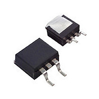
IGBT 10A C410V CLAMPED D2PAK
Manufacturer
STMicroelectronics
Series
PowerMESH™r
Datasheet
1.STGB10NB37LZT4.pdf
(15 pages)
Specifications of STGB10NB37LZ
Voltage - Collector Emitter Breakdown (max)
440V
Vce(on) (max) @ Vge, Ic
1.8V @ 4.5V, 10A
Current - Collector (ic) (max)
20A
Power - Max
125W
Input Type
Logic
Mounting Type
Surface Mount
Package / Case
D²Pak, TO-263 (2 leads + tab)
Channel Type
N
Configuration
Single
Collector-emitter Voltage
375V
Collector Current (dc) (max)
20A
Gate To Emitter Voltage (max)
12V
Pin Count
2 +Tab
Mounting
Surface Mount
Operating Temperature (max)
175C
Operating Temperature Classification
Military
Lead Free Status / RoHS Status
Lead free / RoHS Compliant
Igbt Type
-
Lead Free Status / Rohs Status
Compliant
Available stocks
Company
Part Number
Manufacturer
Quantity
Price

Company:
Part Number:
STGB10NB37LZT4
Manufacturer:
DIODES
Quantity:
15 000


STGB10NB37LZ, STGP10NB37LZ
Table 7.
Table 8.
1. Eon is the tun-on losses when a typical diode is used in the test circuit in figure 2. If the IGBT is offered in
2. Turn-off losses include also the tail of the collector current
Symbol
(di/dt)
Symbol
t
t
E
E
E
E
t
t
t
r
r
a package with a co-pak diode, the co-pack diode is used as external diode. IGBTs & Diode are at the
same temperature (25 °C and 125 °C)
d
d
d(on)
(V
(V
E
E
on
off
on
off
(
(
t
t
t
t
t
off
off
c
c
r
f
f
ts
ts
off
off
(1)
(2)
(1)
(2)
on
)
)
)
)
Turn-on delay time
Current rise time
Turn-on current slope
Cross-over time
Off voltage rise time
Delay time
Fall time
Cross-over time
Off voltage rise time
Delay time
Fall time
Turn-on switching losses
Turn-off switching losses
Total switching losses
Turn-on switching losses
Turn-off switching losses
Total switching losses
Switching on/off (inductive load)
Switching energy (inductive load)
Parameter
Parameter
Doc ID 7402 Rev 4
V
R
(see
V
R
T
V
R
(see
V
R
(see
V
R
T
(see
J
CC
CC
J
G
G
CC
CC
CC
G
G
G
= 125 °C (see
= 1 kΩ, V
= 1 kΩ, V
= 125 °C
= 1 kΩ, V
= 1 KΩ, V
= 1 kΩ, V
= 328 V, I
= 328 V, I
Figure
= 328 V, I
= 328 V, I
= 328 V, I
Figure
Figure
Figure
Test conditions
Test conditions
19)
GE
GE
19)
19)
19)
GE
GE
GE
C
C
C
C
C
= 5 V
= 5 V,
= 5 V,
= 5 V
= 5 V
= 10 A
= 10 A
= 10 A
= 10 A
= 10 A
Figure
19)
Electrical characteristics
Min.
Min.
1300
Typ.
Typ.
270
11.3
3.6
1.4
5.7
2.7
9.2
2.8
2.4
7.4
2.6
8.7
60
2
8
5
Max.
Max.
A/µs
Unit
Unit
ns
ns
µs
µs
µs
µs
µs
µs
µs
µs
mJ
mJ
mJ
mJ
mJ
mJ
5/15
Related parts for STGB10NB37LZ
Image
Part Number
Description
Manufacturer
Datasheet
Request
R

Part Number:
Description:
STMicroelectronics [RIPPLE-CARRY BINARY COUNTER/DIVIDERS]
Manufacturer:
STMicroelectronics
Datasheet:
Part Number:
Description:
STMicroelectronics [LIQUID-CRYSTAL DISPLAY DRIVERS]
Manufacturer:
STMicroelectronics
Datasheet:

Part Number:
Description:
BOARD EVAL FOR MEMS SENSORS
Manufacturer:
STMicroelectronics
Datasheet:
Part Number:
Description:
NPN TRANSISTOR POWER MODULE
Manufacturer:
STMicroelectronics
Datasheet:
Part Number:
Description:
TURBOSWITCH ULTRA-FAST HIGH VOLTAGE DIODE
Manufacturer:
STMicroelectronics
Datasheet:
Part Number:
Description:
Manufacturer:
STMicroelectronics
Datasheet:
Part Number:
Description:
DIODE / SCR MODULE
Manufacturer:
STMicroelectronics
Datasheet:
Part Number:
Description:
DIODE / SCR MODULE
Manufacturer:
STMicroelectronics
Datasheet:
Part Number:
Description:
Search -----> STE16N100
Manufacturer:
STMicroelectronics
Datasheet:
Part Number:
Description:
Search ---> STE53NA50
Manufacturer:
STMicroelectronics
Datasheet:
Part Number:
Description:
NPN Transistor Power Module
Manufacturer:
STMicroelectronics
Datasheet:
Part Number:
Description:
DIODE / SCR MODULE
Manufacturer:
STMicroelectronics
Datasheet: