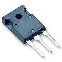
IKW40N120T2 Infineon Technologies, IKW40N120T2 Datasheet - Page 11

IKW40N120T2
Manufacturer Part Number
IKW40N120T2
Description
IGBT 1200V 75A 480W TO247-3
Manufacturer
Infineon Technologies
Series
TrenchStop™r
Datasheet
1.IKW40N120T2.pdf
(15 pages)
Specifications of IKW40N120T2
Igbt Type
Trench
Voltage - Collector Emitter Breakdown (max)
1200V
Vce(on) (max) @ Vge, Ic
2.2V @ 15V, 40A
Current - Collector (ic) (max)
75A
Power - Max
480W
Input Type
Standard
Mounting Type
Through Hole
Package / Case
TO-247-3 (Straight Leads)
Transistor Type
IGBT
Dc Collector Current
40A
Collector Emitter Voltage Vces
2.2V
Power Dissipation Max
480W
Collector Emitter Voltage V(br)ceo
1.2kV
Operating Temperature Range
-40°C To +175°C
Transistor Case Style
TO-247
Rohs Compliant
Yes
Switching Frequency
TRENCHSTOP2 2-20kHz
Package
TO-247
Vce (max)
1,200.0 V
Ic(max) @ 25°
75.0 A
Ic(max) @ 100°
40.0 A
Lead Free Status / RoHS Status
Lead free / RoHS Compliant
Available stocks
Company
Part Number
Manufacturer
Quantity
Price
Company:
Part Number:
IKW40N120T2
Manufacturer:
INFINEON
Quantity:
12 000
Company:
Part Number:
IKW40N120T2
Manufacturer:
INFINEO48
Quantity:
840
Part Number:
IKW40N120T2
Manufacturer:
INFINEON/英飞凌
Quantity:
20 000
Power Semiconductors
Figure 23. Typical reverse recovery time as a
Figure 25. Typical reverse recovery current as
40A
35A
30A
25A
20A
15A
10A
5A
0A
600ns
500ns
400ns
300ns
200ns
100ns
400A/µs
0ns
400A/µs
di
di
function of diode current slope
(V
Dynamic test circuit in Figure E)
a function of diode current slope
(V
Dynamic test circuit in Figure E)
F
F
R
R
/dt,
/dt,
=600V, I
=600V, I
800A/µs
DIODE CURRENT SLOPE
DIODE CURRENT SLOPE
800A/µs
F
F
=40A,
=40A,
1200A/µs
1200A/µs
1600A/µs
T
T
J
T
J
T
=25°C
1600A/µs
=175°C
J
J
=25°C
=175°C
TrenchStop
11
Figure 24. Typical reverse recovery charge as
Figure 26. Typical diode peak rate of fall of
-1000A/µs
8µC
6µC
4µC
2µC
0µC
®
-800A/µs
-600A/µs
-400A/µs
-200A/µs
2
-0A/µs
400A/µs
nd
Generation Series
400A/µs
a function of diode current slope
(V
Dynamic test circuit in Figure E)
reverse recovery current as a
function of diode current slope
(V
Dynamic test circuit in Figure E)
di
di
F
F
R
R
/dt,
/dt,
=600V, I
=600V, I
800A/µs
DIODE CURRENT SLOPE
DIODE CURRENT SLOPE
800A/µs
IKW40N120T2
F
F
=40A,
=40A,
1200A/µs
1200A/µs
Rev. 2.2
T
1600A/µs
T
J
1600A/µs
J
=25°C
=175°C
T
T
J
J
=175°C
=25°C
Sep 08


