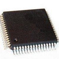
CS44600-CQZR Cirrus Logic Inc, CS44600-CQZR Datasheet - Page 42

CS44600-CQZR
Manufacturer Part Number
CS44600-CQZR
Description
Audio Amplifiers 6ch 24-bit 192kHz Dig. Amp Cntrlr T&R
Manufacturer
Cirrus Logic Inc
Datasheet
1.CS44600-CQZ.pdf
(76 pages)
Specifications of CS44600-CQZR
Operating Supply Voltage
2.5 V
Supply Current
150 mA
Maximum Operating Temperature
+ 70 C
Mounting Style
SMD/SMT
Minimum Operating Temperature
- 10 C
Supply Type
Digital
Supply Voltage (max)
2.62 V
Supply Voltage (min)
2.37 V
Package / Case
LQFP-64
Lead Free Status / RoHS Status
Lead free / RoHS Compliant
42
5.1.3
6. When driving a single-ended (half-bridged) power output stage, set the RAMP[1:0] bits to ‘11’b and
7. Set the PDN bit to ‘0’b to take the CS44600 out of the power-down state.
8. Start all clocks on the DAI interface (DAI_MCLK, DAI_SCLK, DAI_LRCK). This will initiate the SRC to
9. Wait for the SRC to lock.
10. If using the PSR feedback, jump to
11. Set the appropriate GPIO pin, or other control signal, to enable the power output stage.
12. Enable each channel’s PWM modulator by setting the PDN_PWMxx bit to ‘0’b. If full-bridged, go to
13. Wait for the ramp-up sequence to complete. The ramp-up function can be configured to cause an
14. For full-bridged power output stage configurations, the ramp-up sequence is not required. Enabling
15. If using the PSR feedback, set the FEEDBACK_EN bit to ‘1’b.
16. Un-mute all active channels.
17. At this point, the CS44600 is ready to accept audio samples and begin playback.
1. Set the DEC_SHIFT[2:0]/DEC_SCALE[18:0] coefficient (C
2. Set the PSR_RESET bit to ‘1’b.
3. Set the PSR_EN bit to ‘1’b.
4. Set the PSR_EN bit to ‘0’b.
5. Read DEC_OUTD[23:0].
6. See
7. Continue Recommended Power-Up Sequence.
Recommended PSR Calibration Sequence
the required ramp speed, to initiate a ramp cycle when the channel is powered on. Set
MIN_PULSE[4:0] to ‘00000’b.
begin the lock sequence. The SRC lock function can be configured to cause an interrupt condition
when lock has been completed. This will be indicated by an active INT signal.
finished, continue to step 12. If not using PSR feedback, continue to step 12.
step 14. If single-ended (half-bridged), this will initiate a sequence which will slowly increase the DC
voltage, from 0V to Vpower÷2, across the AC coupling capacitor. This will eliminate the instantaneous
charge across the capacitor which would have caused an audible pop from the speaker.
interrupt condition when the ramp period has completed. This will be indicated by an active INT signal.
Once the ramp-up sequence has completed, set the RAMP[1:0] bits to ‘01’b
the power output stage will not cause an audible pop from the speaker.
36h = 00h, 37h = 00h).
Figure 30
to adjust the DEC_SHIFT[2:0]/DEC_SCALE[18:0] registers.
“Recommended PSR Calibration Sequence” on page
PSR
) to decimal 1.0 (register 35h = 22h,
CS44600
44. When
DS633F1


