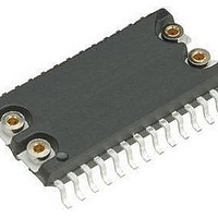
M41ST85WMH6 STMicroelectronics, M41ST85WMH6 Datasheet - Page 31

M41ST85WMH6
Manufacturer Part Number
M41ST85WMH6
Description
Real Time Clock RO 511-M41ST85WMH6E
Manufacturer
STMicroelectronics
Datasheet
1.M41ST85WMH6.pdf
(41 pages)
Specifications of M41ST85WMH6
Function
Clock, Calendar, Supervisor, Alarm
Rtc Memory Size
64 B
Supply Voltage (max)
3.6 V
Supply Voltage (min)
2.7 V
Maximum Operating Temperature
+ 85 C
Minimum Operating Temperature
- 40 C
Mounting Style
SMD/SMT
Rtc Bus Interface
Serial
Package / Case
SO-28
Time Format
HH:MM:SS:hh
Lead Free Status / RoHS Status
Lead free / RoHS Compliant
Available stocks
Company
Part Number
Manufacturer
Quantity
Price
Part Number:
M41ST85WMH6
Manufacturer:
ST
Quantity:
20 000
Part Number:
M41ST85WMH6F
Manufacturer:
ST
Quantity:
20 000
M41ST85W
Table 11.
1. Valid for ambient operating temperature: T
2. Measured with V
3. RSTIN1 and RSTIN2 internally pulled-up to V
4. Outputs deselected.
5. External SRAM must match RTC supervisor chip V
6. For rechargeable backup, V
7. For PFO and SQW pins (CMOS).
8. Conditioned output (E
9. For IRQ/FT/OUT, RST pins (open drain): if pulled-up to supply other than V
I
V
OUT1
I
I
I
V
BAT
V
Sym
OHB
I
V
I
I
OUT2
V
V
LO
V
V
CC1
CC2
LI
V
100 K
will reduce battery life.
3.0 V when V
PFD
BAT
OH
PFI
SO
OL
IH
(3)
IL
(4)
(2)
(8)
(5)
Battery current OSC ON
Battery current OSC OFF
Supply current
Supply current (standby)
Input leakage current
Input leakage current (PFI)
Output leakage current
V
V
Input high voltage
Input low voltage
Battery voltage
Output high voltage
Pull-up supply voltage (open drain)
V
Output low voltage
Output low voltage (open drain)
Power fail deselect
PFI input threshold
PFI hysteresis
Battery backup switchover
resistor.
OUT
OUT
OH
DC characteristics
(battery backup)
CC
current (active)
current (battery backup)
= 0 V (during battery backup mode).
OUT
Parameter
and E
CON
) can only sustain CMOS leakage current in the battery backup mode. Higher leakage currents
CON
BAT
(7)
open.
(max) may be considered V
A
(9)
= –40 to 85°C; V
CC
T
through 100 K
A
CC
= 25°C, V
SCL, SDA = V
specification.
V
V
OUT2
RST, IRQ/FT/OUT
Test condition
OUT1
I
0V
0V
OUT2
or V
I
V
OH
I
CC
I
f = 400 kHz
OL
OL
CC
CC
PFI rising
.
> V
CC
> V
= –1.0 mA
SS
= 3.0 mA
= 10 mA
= 2.7 to 3.6 V (except where noted).
V
V
= 3 V(W)
= –1.0 µA
resistor. WDI internally pulled-down to V
= 0 V, V
IN
IN
BAT
+ 0.3 V
CC
CC
– 0.3 V
– 0.3 V
V
V
– 0.3 V
CC
CC
(1)
BAT
CC
, this supply must be equal to, or less than
= 3 V
0.7V
1.225
–0.3
2.55
Min
–25
2.5
2.4
2.5
CC
M41ST85W
DC and AC parameters
1.250
2.60
Typ
400
3.0
2.9
2.5
50
20
2
SS
V
0.3V
CC
1.275
3.5
through
Max
0.75
0.50
2.70
500
100
100
3.6
3.5
0.4
0.4
±1
25
±1
70
+ 0.3
(6)
CC
Unit
mA
mA
mA
mV
31/41
nA
nA
µA
nA
µA
µA
V
V
V
V
V
V
V
V
V
V
V


