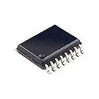
Si3016-KS Silicon Laboratories Inc, Si3016-KS Datasheet - Page 18

Si3016-KS
Manufacturer Part Number
Si3016-KS
Description
Telecom Line Management ICs Line-Side device for processors
Manufacturer
Silicon Laboratories Inc
Type
Chipsetr
Datasheet
1.SI3016-F-FS.pdf
(50 pages)
Specifications of Si3016-KS
Product
Modem Module
Interface Type
Wire
Supply Current
0.3 mA
Maximum Operating Temperature
+ 70 C
Minimum Operating Temperature
0 C
Mounting Style
SMD/SMT
Package / Case
SOIC-16
Lead Free Status / RoHS Status
Lead free / RoHS Compliant
Available stocks
Company
Part Number
Manufacturer
Quantity
Price
Part Number:
SI3016-KS
Manufacturer:
SI
Quantity:
20 000
Part Number:
Si3016-KSR
Manufacturer:
SILICON LABS/èٹ¯ç§‘
Quantity:
20 000
Si3016
off-hook. This will satisfy the Australian dc termination
requirements.
4.10. AC Termination
The Si3016 has two ac Termination impedances, which
are selected with the ACT bit.
ACT = 0 is a real, nominal 600 Ω termination, which
satisfies the impedance requirements of FCC part 68,
JATE, and other countries. This real impedance is set
by circuitry internal to the Si3016 as well as the resistor
R2 connected to the REXT pin.
ACT = 1 is a complex impedance, which satisfies the
impedance requirements of Australia, New Zealand,
South Africa, CTR21, and some European NET4
countries, such as the UK and Germany. This complex
impedance is set by circuitry internal to the Si3016 as
well as the complex network formed by R12, R13, and
C14 connected to the REXT2 pin.
4.11. Ring Detection
The ring signal is capacitively coupled from TIP and
RING to the RNG1 and RNG2 pins. The Si3016
supports either full- or half-wave ring detection. With
full-wave ring detection, the designer can detect a
polarity reversal as well as the ring signal. See "4.18.
Caller ID" on page 20. The ring detection threshold is
programmable with the RT bit.
The ring detector output can be monitored in one of two
ways. The first method uses the register bits, RDTP,
RDTN, and RDT. The second method uses the SDO
output internal to the integrated system-side module.
The DSP must detect the frequency of the ring signal in
order to distinguish a ring from pulse dialing by
telephone equipment connected in parallel.
A positive ringing signal is defined as a voltage greater
than the ring threshold across RNG1-RNG2. RNG1 and
RNG2 are pins 5 and 6 of the Si3016. Conversely, a
negative ringing signal is defined as a voltage less than
the negative ring threshold across RNG1-RNG2.
The first ring detect method uses the ring detect bits,
RDTP, RDTN, and RDT. RDTP and RDTN behavior is
based on the RNG1-RNG2 voltage. Whenever the
signal on RNG1-RNG2 is above the positive ring
threshold, the RDTP bit is set. Whenever the signal on
RNG1-RNG2 is below the negative ring threshold, the
RDTN bit is set. When the signal on RNG1-RNG2 is
between these thresholds, neither bit is set.
The RDT behavior is also based on the RNG1-RNG2
voltage. When the RFWE bit is a 0 or a 1, a positive
ringing signal will set the RDT bit for a period of time.
The RDT bit will not be set for a negative ringing signal.
18
Rev. 1.0
The RDT bit acts as a one shot. Whenever a new ring
signal is detected, the one shot is reset. If no new ring
signals are detected prior to the one shot counter
counting down to zero, the RDT bit will return to zero.
The length of this count (in seconds) is 65536 divided
by the sample rate. The RDT will also be reset to zero
by an off-hook event.
The second ring detect method uses the internal serial
output of the integrated system-side module (SDO) to
transmit ring data. If the link is active (PDL = 0) and the
device is not off-hook or not in on-hook line monitor
mode, the ring data will be sent by the system-side
module to the host processor. The waveform on SDO
depends on the state of the RFWE bit.
When the RFWE bit is 0, SDO will be –32768 (0x8000)
while the RNG1-RNG2 voltage is between the
thresholds. When a ring is detected, SDO will transition
to +32767 while the ring signal is positive, then go back
to –32768 while the ring is near zero and negative.
Thus, a near square wave is presented on SDO that
swings from –32768 to +32767 in cadence with the ring
signal.
When the RFWE bit is 1, SDO will sit at approximately
+1228 while the RNG1-RNG2 voltage is between the
thresholds. When the ring goes positive, SDO will
transition to +32767. When the ring signal goes near
zero, SDO will remain near 1228. Then, as the ring
goes negative, the SDO will transition to –32768. This
will repeat in cadence with the ring signal.
The best way to observe the ring signal on SDO is
simply to observe the MSB of the data. The MSB will
toggle in cadence with the ring signal independent of
the ring detector mode. This is adequate information for
determining the ring frequency. The MSB of SDO will
toggle at the same frequency as the ring signal.
4.12. Ringer Impedance
The ring detector in many DAAs is ac-coupled to the
line with a large, 1 µF, 250 V decoupling capacitor. The
ring detector on the Si3016 is also capacitively coupled
to the line, but it is designed to use smaller, less
expensive 1.8 nF capacitors. Inherently, this network
produces a high ringer impedance to the line of
approximately 800 to 900 kΩ. This value is acceptable
for the majority of countries, including FCC and CTR21.
Several countries including Poland, South Africa, and
Slovenia, require a maximum ringer impedance that can
be met with an internally-synthesized impedance by
setting the RZ bit in Register 16.


