72-8155 TENMA, 72-8155 Datasheet
72-8155
Specifications of 72-8155


72-8155 Summary of contents
Page 1
... Model 72-8155: OPERATING MANUAL Table of Contents Title Overview Inspection Safety Information Rules For Safe Operation International Electrical Symbols The Meter Structure Functional Buttons Display Symbols Measurement Operation A. Measuring Resistance B. Diode and Continuity Test C. Capacitance Measurement D. Inductance Measurement E. Transistor hFE Measurement General Specifications Accuracy Specifications A ...
Page 2
... Model 72-8155: OPERATING MANUAL 2 ...
Page 3
... Digital Inductance Capacitance Meter Model 72-8155 (hereafter referred to as “the Meter” 1/2 digits with steady operations, fashionable design and highly reliable hand-held measuring instrument. The Model 72-8155 will measure capacitance, inductance, resistance, transistor hFE and test diodes. It will also test continuity with an audible buzzer. 3 ...
Page 4
... Meter or the equipment under test. A Note identifies the information that user should pay attention to. International electrical symbols used on the Meter and in this Operating Manual are explained on page 7. Model 72-8155: OPERATING MANUAL Qty 1 piece 1 pair 1 piece 4 ...
Page 5
... Model 72-8155: OPERATING MANUAL Rules For Safe Operation Warning To avoid possible electric shock or personal injury, and to avoid possible damage to the Meter or to the equipment under test, adhere to the following rules: l Before using the Meter inspect the case. Do not use the Meter damaged or the case (or part of the case) is removed ...
Page 6
... Meter from corrosion, damage and accident. l Remove the battery when not used for a prolonged period to avoid damage to the Meter. l Periodically check the battery as it may leak after some time. If leakage is apparent, the battery should be immediately replaced to prevent damage to the Meter. Model 72-8155: OPERATING MANUAL 6 ...
Page 7
... Model 72-8155: OPERATING MANUAL International Electrical Symbols Ground Double Insulated Low Battery. Continuity Test. Diode. Capacitance Test Lx Inductance Test Fuse. Warning. Refer to the Operating Manual. Conforms to Standards of European Union. 7 ...
Page 8
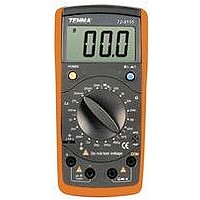
... The Meter Structure 1. LCD Display 2. L-C switch 3. Transistor Jack 4. Resistance, Diode and Continuity Input Terminal 5. Capacitance and Inductance Input Terminal 6. Rotary Switch 7. Power. Model 72-8155: OPERATING MANUAL (see figure 1) (figure 1) 8 ...
Page 9
... Model 72-8155: OPERATING MANUAL Functional Buttons The following table provides information regarding the functional button operation. Button Description Press the Power down to turn the Meter on. Power Press the Power again to turn the Meter power off. Press L-C down to enter the Capacitance measurement mode ...
Page 10
... Picofarad farads. nF: Nanofarad farads. µF: Microfarad µF mF: Millifarad Ohm. The unit of resistance kilohm 1000 ohms Megaohm 1,000,000 ohms M H: Henry. The unit of Inductance mH: Millihenry Model 72-8155: OPERATING MANUAL (figure 2) -12 or 0.000000000001 -9 or 0.000000001 -6 or 0.000001 farads 0.001 farads 0.001 henry. 10 ...
Page 11
... Model 72-8155: OPERATING MANUAL Measurement Operation l Make sure the Low Battery Display otherwise false readings may be provided. l Pay extra attention to the measurement, which is located besides the input terminals of the Meter. A. Measuring Resistance Warning To avoid damage to the Meter or to the devices under test, disconnect circuit power and discharge all the high-voltage capacitors before measuring resistance ...
Page 12
... When resistance measurement has been completed, disconnect the connection between the test clips and the circuit under test and remove the test clips from the input terminals of the Meter. Model 72-8155: OPERATING MANUAL and 200 range, the test clips 12 ...
Page 13
... Model 72-8155: OPERATING MANUAL Warning To avoid damage to the Meter or to the devices under test, disconnect circuit power and discharge all the high-voltage capacitors before measuring diodes and continuity. Testing Diodes Use the diode test to check diodes, transistors, and other semiconductor devices. The diode test sends a current through the semiconductor junction, and then measures the voltage drop across the junction ...
Page 14
... The LCD displays “1” indicating the circuit being tested is open. l When continuity test has been completed, disconnect the connection between the test clips and the circuit under test and remove the test clips from the input terminals of the Meter. Model 72-8155: OPERATING MANUAL terminal and . 14 ...
Page 15
... Model 72-8155: OPERATING MANUAL C. Capacitance Measurement (72-8155 only, see figure 5) Warning To avoid damage to the Meter or to the equipment under test, disconnect circuit power and discharge all high-voltage capacitors before measuring capacitance. The Meter’s capacitance ranges are: 2nF, 20nF, 200nF, 2µF, 20µF, 200µF and 600µF. ...
Page 16
... You need to use other tools or equipment to check and confirm. When capacitance measurement has been completed, disconnect the connection between the test clips and the circuit under test and remove the test clips from the input terminals of the Meter. Model 72-8155: OPERATING MANUAL 16 ...
Page 17
... Model 72-8155: OPERATING MANUAL D. Inductance Measurement (see figure 6) To test the inductance, please follow the following procedure: 1. Set the rotary switch to Lx measurement mode the tested inductance value is unknown, use the maximum measurement position and decrease the range step by step until a satisfactory reading is obtained. ...
Page 18
... The Meter displays the tested transistor’s nearest value Note: l When transistor measurement has been completed, disconnect the connection between the test clips and the circuit under test and remove the test clips from the input terminals of the Meter. Model 72-8155: OPERATING MANUAL (figure 7) 18 ...
Page 19
... Model 72-8155: OPERATING MANUAL General Specifications l Fuse Protection for Inductance and capacitance Input Terminal: 0.315A, 250V, fast type fuse, 5x20 mm. l Maximum Display: Display: 1999. l Measurement Speed: Updates 2-3 times /second. l Polarity: Auto. (Display “-“ when negative) l Overloading: Display “1” ...
Page 20
... During measurement minus these 12 digits from the obtained reading. l When measuring 20 and 200 clips to display the resistance value of the test lead. Subtract this value from the measurement value to obtain the correct tested value. Model 72-8155: OPERATING MANUAL Accuracy (0.8%+3) (0 ...
Page 21
... Model 72-8155: OPERATING MANUAL B. Continuity & Diodes Function Range Diode Continuity Remarks: l Diode: Open Circuit Voltage around 5.8V, forward current around 1mA. l Continuity 10 , beeper sounds continuously. > beeper may or may not sound. C. Capacitance Test Range Resolution 2.000nF 0.001nF 20.00nF 0.01nF 200.0nF 0.1nF 2.000µ ...
Page 22
... Remarks: l Measure of Inductance: 1H=10 l Overload Protection: 0.315A, 250V, fast type fuse, 5x20 mm E. Transistor Range Resolution Condition Vce hFE Model 72-8155: OPERATING MANUAL Tested Frequ- Accuracy ency / Current (2%+8) 1kHz/150µA (5%+5) 100Hz/15µA (5%+15 µ . Testing Remarks The display value is the 5.8V tested transistor’ ...
Page 23
... Model 72-8155: OPERATING MANUAL Maintenance This section provides basic maintenance information including battery and fuse replacement instruction. Warning Do not attempt to repair or service your Meter unless you are qualified and have the relevant calibration, performance test, and service information. To avoid electrical shock or damage to the Meter, do not allow water inside the case ...
Page 24
... Remove the battery from the battery compartment. 4. Replace the battery with a new 9V alkaline battery (NEDA1604 or 0062 or 6F22 or 006P) 5. Replace the case bottom and battery compartment, and reinstall the screw. Model 72-8155: OPERATING MANUAL (see figure 8) (figure 8) ” appears. 24 ...
Page 25
... Model 72-8155: OPERATING MANUAL C. Replacing the Fuse (see figure 9) Warning To avoid injury due to electrical shock or arc blast, and to avoid damage to the Meter, use specified fuses ONLY in accordance with the following procedure. To replace the Meter’s fuse: 1. Turn the Meter power off and remove all connections from the terminals ...
Page 26
... Copyright 2006 Tenma Test Equipment. All rights reserved. Tenma Test Equipment 405 S. Pioneer Blvd. Springboro,Ohio 45066 www.tenma.com Model 72-8155: OPERATING MANUAL 26 ...