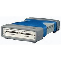
U2353A AGILENT TECHNOLOGIES, U2353A Datasheet - Page 26

U2353A
Manufacturer Part Number
U2353A
Description
USB Modular Data Acquisition
Manufacturer
AGILENT TECHNOLOGIES
Datasheet
1.U2352A.pdf
(75 pages)
Specifications of U2353A
No. Of Channels
16
Sampling Rate
1MSPS
Input Voltage Max
12V
Input Current Max
2A
Bandwidth
400kHz
External Height
44mm
External Width
120mm
External Depth
182.4mm
Sample Rate
500 KSa/s
Lead Free Status / RoHS Status
na
Product specifi cations
Model number
Analog input
Resolution
Number of channels
Maximum sampling rate
Programmable bipolar input range
Programmable unipolar input range
Input coupling
Input impedance
Operational common mode voltage range
Overvoltage range
Trigger sources
Trigger modes
FIFO buffer size
Analog output
Resolution
Number of channels
Maximum update rate
Output ranges
Output coupling
Output impedance
Stability
Power-on state
Trigger sources
Trigger modes
FIFO buffer size
Glitch energy
Driving capability
Function generation mode
Digital input/output
Number of bits
Compatibility
Input voltage
Input voltage range
Output voltage
General purpose digital timer/counter
Maximum count
Number of channels
Compatibility
Clock source
Base clock available
Maximum clock source frequency
Input frequency range
Pulse width measurement range
[4]
[1]
2 MSa/s
U2531A
14 bits
4 differential input channels (software selectable/channel)
Power-on: Continuous ±30 V, Power-off: Continuous ±15 V
Pre-trigger, delay-trigger, post-trigger, and middle-trigger
Sine, square, triangle, sawtooth, and noise waveforms
0 to 10 V, ±10 V, 0 to AO_EXT_REF, ±AO_EXT_REF
External analog/digital trigger, SSI/star trigger
External analog/digital trigger, SSI/star trigger
VOH = 2.4 V minimum; IOH = 400 μA maximum
VOL = 0.45 V maximum; IOL = 8 mA maximum
26
VIL = 0.7 V maximum; IIL = 10 μA maximum
VIH = 2.0 V minimum; IIH = 10 μA maximum
0 to 10 V, 0 to 5 V, 0 to 2.5 V, 0 to 1.25 V
4 Channels used: Maximum 2 MSa/ch
5 ns-V (Typical), 80 ns-V (Maximum)
24-bit programmable input/output
0.1 Hz to 6 MHz at 50% duty cycle
1 Channel used: Maximum 8 MSa
2 Independent up/down counter
0.167 μs to 178.956 s ±0.0833 μs
Any passive load up to 1500 pF
±10 V, ±5 V, ±2.5 V, ±1.25 V
Delay trigger, post trigger
Internal or external
±8.0 V maximum
0 V steady state
–0.5 V to +5.5 V
0.1 Ω Typical
(231 – 1) bits
1 GΩ/100 pF
Up to 8 MSa
250 kSa/s
1 MSa/s
U2541A
48 MHz
12 MHz
12 Bits
5 mA
TTL
TTL
DC
DC
2
16 bits
[2]
[2]
[3]
500 kSa/s
U2542A


