SI7465DP-T1-E3 Vishay, SI7465DP-T1-E3 Datasheet - Page 10
SI7465DP-T1-E3
Manufacturer Part Number
SI7465DP-T1-E3
Description
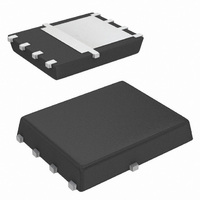
MOSFET P-CH 60V 3.2A PPAK 8SOIC
Manufacturer
Vishay
Series
TrenchFET®r
Type
Power MOSFETr
Specifications of SI7465DP-T1-E3
Transistor Polarity
P-Channel
Fet Type
MOSFET P-Channel, Metal Oxide
Fet Feature
Logic Level Gate
Rds On (max) @ Id, Vgs
64 mOhm @ 5A, 10V
Drain To Source Voltage (vdss)
60V
Current - Continuous Drain (id) @ 25° C
3.2A
Vgs(th) (max) @ Id
3V @ 250µA
Gate Charge (qg) @ Vgs
40nC @ 10V
Power - Max
1.5W
Mounting Type
Surface Mount
Package / Case
PowerPAK® SO-8
Minimum Operating Temperature
- 55 C
Configuration
Single Quad Drain Triple Source
Resistance Drain-source Rds (on)
0.064 Ohm @ 10 V
Drain-source Breakdown Voltage
60 V
Gate-source Breakdown Voltage
+/- 20 V
Continuous Drain Current
3.2 A
Power Dissipation
1500 mW
Maximum Operating Temperature
+ 150 C
Mounting Style
SMD/SMT
Continuous Drain Current Id
-5A
Drain Source Voltage Vds
-60V
On Resistance Rds(on)
80mohm
Rds(on) Test Voltage Vgs
20V
Threshold Voltage Vgs Typ
-3V
Number Of Elements
1
Polarity
P
Channel Mode
Enhancement
Drain-source On-res
0.064Ohm
Drain-source On-volt
60V
Gate-source Voltage (max)
±20V
Operating Temp Range
-55C to 150C
Operating Temperature Classification
Military
Mounting
Surface Mount
Pin Count
8
Package Type
PowerPAK SO
Lead Free Status / RoHS Status
Lead free / RoHS Compliant
Lead Free Status / RoHS Status
Lead free / RoHS Compliant, Lead free / RoHS Compliant
Other names
SI7465DP-T1-E3TR
Available stocks
Company
Part Number
Manufacturer
Quantity
Price
Company:

Part Number:
SI7465DP-T1-E3
Manufacturer:
Vishay/Siliconix
Quantity:
128 507
Company:
Part Number:
SI7465DP-T1-E3
Manufacturer:
VISHAY
Quantity:
21 676
Part Number:
SI7465DP-T1-E3
Manufacturer:
VISHAY/威世
Quantity:
20 000


AN821
Vishay Siliconix
SYSTEM AND ELECTRICAL IMPACT OF
PowerPAK SO-8
In any design, one must take into account the change in
MOSFET r
A MOSFET generates internal heat due to the current
passing through the channel. This self-heating raises
the junction temperature of the device above that of the
PC board to which it is mounted, causing increased
power dissipation in the device. A major source of this
problem lies in the large values of the junction-to-foot
thermal resistance of the SO-8 package.
PowerPAK SO-8 minimizes the junction-to-board ther-
mal resistance to where the MOSFET die temperature is
very close to the temperature of the PC board. Consider
two devices mounted on a PC board heated to 105 °C
by other components on the board (Figure 8).
www.vishay.com
4
PowerPAK SO-8
Figure 8. Temperature of Devices on a PC Board
1.8
1.6
1.4
1.2
1.0
0.8
0.6
- 50
Figure 7. MOSFET r
DS(on)
- 25
V
I
D
On-Resistance vs. Junction Temperature
GS
0.8 °C/W
with temperature (Figure 7).
= 23 A
= 10 V
PC Board at 105 °C
T
J
0
- Junction Temperature (°C)
107 °C
25
DS(on)
50
vs. Temperature
Standard SO-8
75
100
16 C/W
125
148 °C
150
Suppose each device is dissipating 2.7 W. Using the
junction-to-foot thermal resistance characteristics of the
PowerPAK SO-8 and the standard SO-8, the die tem-
perature is determined to be 107 °C for the PowerPAK
(and for DPAK) and 148 °C for the standard SO-8. This
is a 2 °C rise above the board temperature for the Pow-
erPAK and a 43 °C rise for the standard SO-8. Referring
to Figure 7, a 2 °C difference has minimal effect on
r
on r
Minimizing the thermal rise above the board tempera-
ture by using PowerPAK has not only eased the thermal
design but it has allowed the device to run cooler, keep
r
rent than the same MOSFET die in the standard SO-8
package.
CONCLUSIONS
PowerPAK SO-8 has been shown to have the same
thermal performance as the DPAK package while hav-
ing the same footprint as the standard SO-8 package.
The PowerPAK SO-8 can hold larger die approximately
equal in size to the maximum that the DPAK can accom-
modate implying no sacrifice in performance because of
package limitations.
Recommended PowerPAK SO-8 land patterns are pro-
vided to aid in PC board layout for designs using this
new package.
Thermal considerations have indicated that significant
advantages can be gained by using PowerPAK SO-8
devices in designs where the PC board was laid out for
the standard SO-8. Applications experimental data gave
thermal performance data showing minimum and typical
thermal performance in a SO-8 environment, plus infor-
mation on the optimum thermal performance obtainable
including spreading copper. This further emphasized the
DPAK equivalency.
PowerPAK SO-8 therefore has the desired small size
characteristics of the SO-8 combined with the attractive
thermal characteristics of the DPAK package.
DS(on)
DS(on)
DS(on)
whereas a 43C difference has a significant effect
low, and permits the device to handle more cur-
.
Document Number 71622
28-Feb-06
Related parts for SI7465DP-T1-E3
Image
Part Number
Description
Manufacturer
Datasheet
Request
R

Part Number:
Description:
P-channel 60-v D-s Mosfet
Manufacturer:
Vishay
Datasheet:

Part Number:
Description:
MOSFET P-CH 60V 3.2A PPAK 8SOIC
Manufacturer:
Vishay
Datasheet:
Part Number:
Description:
357-036-542-201 CARDEDGE 36POS DL .156 BLK LOPRO
Manufacturer:
Vishay
Datasheet:
Part Number:
Description:
357-036-542-201 CARDEDGE 36POS DL .156 BLK LOPRO
Manufacturer:
Vishay
Datasheet:
Part Number:
Description:
357-036-542-201 CARDEDGE 36POS DL .156 BLK LOPRO
Manufacturer:
Vishay
Datasheet:
Part Number:
Description:
357-036-542-201 CARDEDGE 36POS DL .156 BLK LOPRO
Manufacturer:
Vishay
Datasheet:
Part Number:
Description:
357-036-542-201 CARDEDGE 36POS DL .156 BLK LOPRO
Manufacturer:
Vishay
Datasheet:
Part Number:
Description:
357-036-542-201 CARDEDGE 36POS DL .156 BLK LOPRO
Manufacturer:
Vishay
Datasheet:
Part Number:
Description:
357-036-542-201 CARDEDGE 36POS DL .156 BLK LOPRO
Manufacturer:
Vishay
Datasheet:
Part Number:
Description:
357-036-542-201 CARDEDGE 36POS DL .156 BLK LOPRO
Manufacturer:
Vishay
Datasheet:
Part Number:
Description:
357-036-542-201 CARDEDGE 36POS DL .156 BLK LOPRO
Manufacturer:
Vishay
Datasheet:
Part Number:
Description:
357-036-542-201 CARDEDGE 36POS DL .156 BLK LOPRO
Manufacturer:
Vishay
Datasheet:
Part Number:
Description:
357-036-542-201 CARDEDGE 36POS DL .156 BLK LOPRO
Manufacturer:
Vishay
Datasheet:
Part Number:
Description:
357-036-542-201 CARDEDGE 36POS DL .156 BLK LOPRO
Manufacturer:
Vishay
Datasheet:
Part Number:
Description:
357-036-542-201 CARDEDGE 36POS DL .156 BLK LOPRO
Manufacturer:
Vishay
Datasheet: