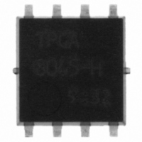
TPCA8045-H(TE12LQM Toshiba, TPCA8045-H(TE12LQM Datasheet - Page 30

TPCA8045-H(TE12LQM
Manufacturer Part Number
TPCA8045-H(TE12LQM
Description
MOSFET N-CH 40V 46A 8-SOP ADV
Manufacturer
Toshiba
Specifications of TPCA8045-H(TE12LQM
Fet Type
MOSFET N-Channel, Metal Oxide
Fet Feature
Standard
Drain To Source Voltage (vdss)
40V
Current - Continuous Drain (id) @ 25° C
46A
Vgs(th) (max) @ Id
2.3V @ 1mA
Mounting Type
Surface Mount
Package / Case
8-SOP
Lead Free Status / RoHS Status
Lead free / RoHS Compliant
Power - Max
-
Gate Charge (qg) @ Vgs
-
Rds On (max) @ Id, Vgs
-
Other names
TPCA8045-HTE12LQMTR
30
As the second-generation series of Schottky barrier diodes, Toshiba has developed new devices with a reverse breakdown
voltage of 30 V. Owing to low peak forward voltage (VFM) and low peak repetitive reverse current (IRRM) characteristics, these
SBDs provide low power loss, help reduce the size and improve the power efficiency of mobile handsets, switching power
supplies, etc., thereby improving their overall performance.
Toshiba has been working to develop the most compact surface-mount packages which allow communication equipment to be
miniaturized.
Toshiba provides high-efficiency diodes
●
●
●
●
(HEDs) with fast reverse recovery to
meet high-efficiency, high-frequency and
low-noise requirements of electronic
equipment. In addition to general HEDs
with the maximum reverse recovery time
of 50 ns, Toshiba has been working to
offer the rank "A" HEDs with the
maximum recovery time of 35 ns.
New Series of Schottky Barrier Diodes
Voltage rating
Current rating
Peak forward voltage (Typical characteristics: CRS10I30A)
Package
Surface-Mount Package Trend for Diodes
HED Reverse Recovery Characteristics
CRS10I30A
CRS10I30B
CRS15I30A
CRS20I30A
CUS10I30A
CUS15I30A
Schottky Barrier Diodes (SBDs) and High-Efficiency Diodes (HEDs)
Part Number
V
(Devices with V
the conventional series.)
I
More devices will be added to provide wider current rating options.
V
Small surface-mount packages (US-FLAT/S-FLAT)
Devices will be available in M-FLAT and TO-220 packages.
F(AV)
RRM
FM
Diodes
= 0.35 Vtyp. (0.39 V Max(@I
= 1 A to 2 A
= 30 V
Packaging
S-FLAT
S-FLAT
S-FLAT
S-FLAT
US-FLAT
US-FLAT
160
150
140
130
120
110
100
90
80
70
60
0
<SBD>
I
V
US-FLAT
F(AV)
RRM
RRM
= 1.0 A
50 mm
= 30 to 60 V
of 40 V to 60 V will be added to
V
6 mm
RRM
30
30
30
30
30
30
5
(V)
S-FLAT
Glass-epoxy board (Board size: 50 mm , Solder land: 6 mm )
<SBD>
I
V
<HED>
I
V
F(AV)
F(AV)
V
RRM
RRM
FM
F(AV)
Footprint and Thermal Resistance
1.0
1.0
1.5
2.0
1.0
1.5
= 1.0 to 2.0 A
= 1.0 A
= 20 to 60 V
= 200 V
= 0.7 A))
AC Input
(A)
10
Absolute Maximum Ratings
M-FLAT
I
FSM
20
20
20
20
20
20
(A)
Active filter
Footprint Area (mm
15
<SBD>
I
V
<HED>
I
V
F(AV)
F(AV)
+
−
T
RRM
RRM
150
150
150
150
150
150
j
(˚C)
= 1.0 to 5.0 A
= 1.0 to 3.0 A
= 30 to 60 V
= 200 to 400 V
20
2
)
−55 to 150
−55 to 150
−55 to 150
−55 to 150
−55 to 150
−55 to 150
T
stg
Tradeoff Relationship between the Forward
Voltage and Reverse Leakage Current (Example)
(˚C)
25
+
−
1000
100
<SBD>
I
V
<HED>
I
V
10
F(AV)
F(AV)
0.25
1
RRM
RRM
= 10 A
= 3.0 to 5.0 A
= 30 to 60 V
= 200 to 400 V
30
New SBDs
I
RRM
0.3
5JLZ47A
0.06
0.06
0.06
0.06
0.06
0.06
5JLZ47
L-FLAT
(mA)
Electrical Characteristics (Max)
0.35
(High-speed product)
V
FM
(V)@I
35
trr
t (ns)
0.4
V
Conventional SBDs
F
FM
0.39
0.42
0.46
0.49
0.39
0.46
= 0.7 A
(V)
0.45
10 ns
(Ta = 25°C)
@I
0.5
200 mA
0.7
1.0
1.5
2.0
0.7
1.5
FM
(A)


