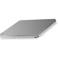
TMC2192KHC Fairchild Semiconductor, TMC2192KHC Datasheet - Page 23

TMC2192KHC
Manufacturer Part Number
TMC2192KHC
Description
Video ICs
Manufacturer
Fairchild Semiconductor
Type
Encoderr
Datasheet
1.TMC2192KHC.pdf
(69 pages)
Specifications of TMC2192KHC
Operating Supply Voltage
- 0.5 V to + 7 V
Supply Current
375 mA
Maximum Operating Temperature
70 C
Package / Case
MQFP-100
Minimum Operating Temperature
0 C
Mounting Style
SMD/SMT
Lead Free Status / RoHS Status
Lead free / RoHS Compliant
Available stocks
Company
Part Number
Manufacturer
Quantity
Price
Company:
Part Number:
TMC2192KHC
Manufacturer:
PHI
Quantity:
90
Part Number:
TMC2192KHC
Manufacturer:
FAIRCHILD/ن»™ç«¥
Quantity:
20 000
PRODUCT SPECIFICATION
Burst Envelope
The TMC2192 includes the ability to adjust the burst ampli-
tude and the shape of the burst. The Control Registers
BRSTFULL, BRST1 and BRST2 hold the magnitude of the
burst vector. BRSTFULL is the maximum amplitude of the
burst vector. BRST1 and BRST2 determine the intermediate
values of the burst vector for the burst envelope shaping. A 5
pixel burst envelope shaping occurs at the rising and falling
edges of burst. At the rising edge of burst the next 5 pixels
have the following weighting; BRSTFULL – BRST1,
BRSTFULL – BRST2, BRSTFULL/2, BRST2, and BRST1.
At the falling edge of burst the next 5 pixels have the follow-
ing weighting; BRST1, BRST2, BRSTFULL/2, BRSTFULL
– BRST2, and BRSTFULL – BRST1. With this flexibility
the user determine the shape, amplitude and width of the
burst signal.
Color-Difference Low-Pass Filters
The chrominance portion of a composite video signal must
be sufficiently bandlimited to avoid cross-color and cross-
luminance distortion, and to preclude exceeding the allow-
able bandwidth of a video channel.
The color-difference low-pass filters on the TMC2192
establish chrominance bandwidths which meet the specifica-
tions outlined in CCIR Report 624-3, Table II, Item 2.6, for
system I over a range of pixel rates from 12.27 Mpps to
14.75 Mpps. Equal bandwidth is established for both color-
difference channels.
Table 12. Line by Line Pedestal Enable
REV. 1.0.0 8/13/03
BRSTFULL - BRST1
Bit
VBIPEDEL
VBIPEDEM
VBIPEDOL
VBIPEDOM
BRSTFULL - BRST2
BLANK
BRSTFULL/2
Figure 15. Burst Envelope
BRST2
BRST1
287*
BRSTFULL
279
25*
17
7
BU
278
286
16
24
6
277
285
15
23
5
65-6294-18
276
284
14
22
4
Sync and Pedestal Insertion
Control Registers for this section
Pedestal Enable
The TMC2192 has the ability to independently select lines
for pedestal insertion during the vertical blanking interval
(VBI). For 525-line systems and using the NTSC line num-
bering convention, in which the first vertical serration is on
line 4 for field 1 and line 266 for field 2, the vertical interval
lines map to the control registers VBIPEDxy as shown in
Table 15.
Address
0x06
0x11
0x14
0x15
0x16
0x17
0x1A
0x3F
-10
-20
-30
-40
-50
-60
-70
-80
0
0
Figure 16. Gaussian Filter Response
275
283
13
21
3
Bit(s)
7-6
5
7-0
7-0
7-0
7-0
6-0
3
0.1
Normalized Frequency (Pixel rate)
274
282
12
20
2
0.2
Name
MODE
COMP2DB
VBIPEDEM
VBIPEDEL
VBIPEDOM
VBIPENOL
PEDHGT1
C2DB_OFF
0.3
273
281
11
19
1
0.4
TMC2192
280
10
18
0
0.5
23


