IRFP360 Vishay, IRFP360 Datasheet - Page 8
IRFP360
Manufacturer Part Number
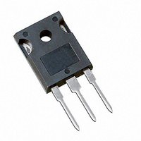
IRFP360
Description
MOSFET N-CH 400V 23A TO-247AC
Manufacturer
Vishay
Series
HEXFET®r
Datasheet
1.IRFP360.pdf
(9 pages)
Specifications of IRFP360
Fet Type
MOSFET N-Channel, Metal Oxide
Fet Feature
Standard
Rds On (max) @ Id, Vgs
200 mOhm @ 14A, 10V
Drain To Source Voltage (vdss)
400V
Current - Continuous Drain (id) @ 25° C
23A
Vgs(th) (max) @ Id
4V @ 250µA
Gate Charge (qg) @ Vgs
210nC @ 10V
Input Capacitance (ciss) @ Vds
4500pF @ 25V
Power - Max
280W
Mounting Type
Through Hole
Package / Case
TO-247-3 (Straight Leads), TO-247AC
Configuration
Single
Transistor Polarity
N-Channel
Resistance Drain-source Rds (on)
0.2 Ohms
Drain-source Breakdown Voltage
400 V
Gate-source Breakdown Voltage
+/- 20 V
Continuous Drain Current
23 A
Power Dissipation
280 W
Maximum Operating Temperature
+ 150 C
Mounting Style
Through Hole
Minimum Operating Temperature
- 55 C
Lead Free Status / RoHS Status
Contains lead / RoHS non-compliant
Other names
*IRFP360
Available stocks
Company
Part Number
Manufacturer
Quantity
Price

Company:
Part Number:
IRFP360
Manufacturer:
IR
Quantity:
12 500
Part Number:
IRFP360
Manufacturer:
IR
Quantity:
20 000
Company:
Part Number:
IRFP360LC
Manufacturer:
IR
Quantity:
12 500
Company:
Part Number:
IRFP360LCPBF
Manufacturer:
FSC
Quantity:
7 000
Part Number:
IRFP360PBF
Manufacturer:
IR
Quantity:
20 000


TO-247AC (HIGH VOLTAGE)
Notes
1. Dimensioning and tolerancing per ASME Y14.5M-1994.
2. Contour of slot optional.
3. Dimension D and E do not include mold flash. Mold flash shall not exceed 0.127 mm (0.005") per side. These dimensions are measured at the
4. Thermal pad contour optional with dimensions D1 and E1.
5. Lead finish uncontrolled in L1.
6. Ø P to have a maximum draft angle of 1.5 to the top of the part with a maximum hole diameter of 3.91 mm (0.154").
7. Outline conforms to JEDEC outline TO-247 with exception of dimension c.
Document Number: 91360
Revision: 15-Sep-08
ECN: S-81920-Rev. A, 15-Sep-08
DWG: 5971
outermost extremes of the plastic body.
DIM.
D1
A1
A2
b1
b2
b3
b4
b5
c1
A
D
b
c
0.10
19.71
13.08
MIN.
4.65
2.21
1.50
0.99
0.99
1.65
1.65
2.59
2.59
0.38
0.38
3
2 x R
5
MILLIMETERS
(2)
2 x b2
R/2
Q
M
L1
3 x b
B
C
C
A
M
1
MAX.
20.70
5.31
2.59
2.49
1.40
1.35
2.39
2.37
3.43
3.38
0.86
0.76
-
2
b4
E
4
E/2
3
2 x e
0.183
0.087
0.059
0.039
0.039
0.065
0.065
0.102
0.102
0.015
0.015
0.776
0.515
MIN.
S
D
L
INCHES
See view B
MAX.
0.209
0.102
0.098
0.055
0.053
0.094
0.093
0.135
0.133
0.034
0.030
0.815
-
D D E
A
A1
C
View B
A2
D
A
A
E
C
Ø P1
DIM.
C
Ø P
Ø k
D2
E1
L1
Q
R
E
N
S
e
L
Thermal pad
Ø k
Planting
D2
15.29
13.72
14.20
MIN.
0.51
3.71
3.56
5.31
4.52
M
7
MILLIMETERS
-
Package Information
D
ØP
5.46 BSC
7.62 BSC
5.51 BSC
(c)
B
0.254
M
Section C - C, D - D, E - E
A
View A - A
0.01
MAX.
15.87
16.10
(b1, b3, b5)
(b, b2, b4)
1.30
4.29
3.66
7.39
5.69
5.49
E1
-
4
5
M
D
(Datum B)
B
Vishay Siliconix
M
(4)
ØP1
0.300 BSC
0.020
0.602
0.540
0.559
0.146
0.140
0.209
0.178
MIN.
D1
-
c1
0.215 BSC
0.217 BSC
Base metal
5
INCHES
www.vishay.com
0.010
MAX.
0.051
0.625
0.634
0.169
0.144
0.291
0.224
0.216
-
1
Related parts for IRFP360
Image
Part Number
Description
Manufacturer
Datasheet
Request
R

Part Number:
Description:
357-036-542-201 CARDEDGE 36POS DL .156 BLK LOPRO
Manufacturer:
Vishay
Datasheet:
Part Number:
Description:
357-036-542-201 CARDEDGE 36POS DL .156 BLK LOPRO
Manufacturer:
Vishay
Datasheet:
Part Number:
Description:
357-036-542-201 CARDEDGE 36POS DL .156 BLK LOPRO
Manufacturer:
Vishay
Datasheet:
Part Number:
Description:
357-036-542-201 CARDEDGE 36POS DL .156 BLK LOPRO
Manufacturer:
Vishay
Datasheet:
Part Number:
Description:
357-036-542-201 CARDEDGE 36POS DL .156 BLK LOPRO
Manufacturer:
Vishay
Datasheet:
Part Number:
Description:
357-036-542-201 CARDEDGE 36POS DL .156 BLK LOPRO
Manufacturer:
Vishay
Datasheet:
Part Number:
Description:
357-036-542-201 CARDEDGE 36POS DL .156 BLK LOPRO
Manufacturer:
Vishay
Datasheet:
Part Number:
Description:
357-036-542-201 CARDEDGE 36POS DL .156 BLK LOPRO
Manufacturer:
Vishay
Datasheet:
Part Number:
Description:
357-036-542-201 CARDEDGE 36POS DL .156 BLK LOPRO
Manufacturer:
Vishay
Datasheet:
Part Number:
Description:
357-036-542-201 CARDEDGE 36POS DL .156 BLK LOPRO
Manufacturer:
Vishay
Datasheet:
Part Number:
Description:
357-036-542-201 CARDEDGE 36POS DL .156 BLK LOPRO
Manufacturer:
Vishay
Datasheet:
Part Number:
Description:
357-036-542-201 CARDEDGE 36POS DL .156 BLK LOPRO
Manufacturer:
Vishay
Datasheet:
Part Number:
Description:
357-036-542-201 CARDEDGE 36POS DL .156 BLK LOPRO
Manufacturer:
Vishay
Datasheet:
Part Number:
Description:
357-036-542-201 CARDEDGE 36POS DL .156 BLK LOPRO
Manufacturer:
Vishay
Datasheet:
Part Number:
Description:
357-036-542-201 CARDEDGE 36POS DL .156 BLK LOPRO
Manufacturer:
Vishay
Datasheet: