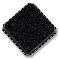
AD5748ACPZ Analog Devices Inc, AD5748ACPZ Datasheet - Page 22

AD5748ACPZ
Manufacturer Part Number
AD5748ACPZ
Description
ZDPLC +/-24V DRIVER
Manufacturer
Analog Devices Inc
Datasheet
1.AD5748ACPZ-RL7.pdf
(32 pages)
Specifications of AD5748ACPZ
Amplifier Type
Instrumentation
Number Of Circuits
1
Slew Rate
2 V/µs
Current - Output / Channel
15mA
Voltage - Supply, Single/dual (±)
±12 V ~ 24 V
Operating Temperature
-40°C ~ 105°C
Mounting Type
Surface Mount
Package / Case
*
No. Of Amplifiers
3
Supply Voltage Range
± 12V To ± 24V
Supply Current
5.2mA
Amplifier Case Style
LFCSP
No. Of Pins
32
Operating Temperature Range
-40°C To +105°C
Svhc
No
Rohs Compliant
Yes
Bandwidth
100kHz
Amplifier Output
Differential
Lead Free Status / RoHS Status
Lead free / RoHS Compliant
Output Type
-
Gain Bandwidth Product
-
-3db Bandwidth
-
Current - Input Bias
-
Voltage - Input Offset
-
Current - Supply
-
Lead Free Status / RoHS Status
Lead free / RoHS Compliant
AD5748
THEORY OF OPERATION
The AD5748 is a single-channel, precision, voltage/current
output driver with hardware or software programmable
output ranges. The software ranges are configured via an SPI-/
MICROWIRE-compatible serial interface. The analog input
to the AD5748 is provided from a low voltage, single-supply,
digital-to-analog converter and is internally conditioned to
provide the desired output current/voltage range. The analog
input range is 0 V to 4.096 V.
The output current range is programmable across two current
ranges: 4 mA to 21 mA and 0 mA to 21 mA.
The voltage output is provided from a separate pin that can
be configured to provide 0 V to 5 V, 0 V to 10.5 V, or ±10.5 V
output ranges. The current and voltage outputs are available on
separate pins. Only one output can be enabled at one time. The
output range is selected by programming the R3 to R0 bits in
the control register (see Table 6 and Table 7).
Figure 49. Typical System Configuration in Software Mode (Pull-Up Resistors Not Shown for Open-Drain Outputs)
MCU
SCLK
SDI/DIN
SDO
SYNC1
VDD
ADP1720
AD506x
AD566x
REFIN
ADR392
SYNC
SCLK
SDIN
SDO
Rev. A | Page 22 of 32
VREF
VIN
HW SELECT
AD5748
INTERFACE
SERIAL
Figure 49 and Figure 50 show a typical configuration of the
AD5748 in software mode and in hardware mode, respectively,
in an output module system. The HW SELECT pin selects
whether the part is configured in software or hardware mode.
The analog input to the AD5748 is provided from a low voltage,
single-supply, digital-to-analog converter (DAC) such as the
AD506x or AD566x, which provides an output range of 0 V
to 4.096 V. The supply and reference for the DAC, as well as
the reference for the AD5748, can be supplied from a reference
such as the ADR392. The AD5748 can operate from supplies
up to ±26.4 V.
SOFTWARE MODE
In current mode, software-selectable output ranges include 0 mA
to 21 mA, and 4 mA to 21 mA.
In voltage mode, software-selectable output ranges include 0 V
to 5 V, 0 V to 10.5 V, and ±10.5 V.
AVDD GND AVSS
VDD AGND VSS
VOUT SHORT FAULT
RANGE
RANGE
SCALE
SCALE
STATUS REGISTER
IOUT OPEN FAULT
OVERTEMP FAULT
VOUT
IOUT
PEC ERROR
FAULT
VSENSE+
VSENSE–
VOUT
0V TO +5V,
0V TO +10.5V,
±10.5V
IOUT
4mA TO 21mA,
0mA TO 21mA


