HMPP-3895-TR1 Avago Technologies US Inc., HMPP-3895-TR1 Datasheet - Page 6
HMPP-3895-TR1
Manufacturer Part Number
HMPP-3895-TR1
Description
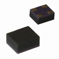
DIODE PIN SWITCH 100V 1A MINIPAK
Manufacturer
Avago Technologies US Inc.
Datasheet
1.HMPP-3890-TR1.pdf
(13 pages)
Specifications of HMPP-3895-TR1
Package / Case
4-MiniPak (1412)
Diode Type
PIN - 2 Independant
Voltage - Peak Reverse (max)
100V
Current - Max
1A
Capacitance @ Vr, F
0.3pF @ 5V, 1MHz
Resistance @ If, F
2.5 Ohm @ 5mA, 100MHz
Configuration
Parallel
Reverse Voltage
5 V
Forward Continuous Current
1 A
Frequency Range
SHF
Termination Style
SMD/SMT
Carrier Life
0.2 us
Maximum Diode Capacitance
0.3 pF at 5 V
Maximum Operating Temperature
+ 150 C
Maximum Series Resistance @ Maximum If
2.5 Ohms at 5 mA
Maximum Series Resistance @ Minimum If
3.8 Ohms at 1 mA
Minimum Operating Temperature
- 65 C
Mounting Style
SMD/SMT
Lead Free Status / RoHS Status
Contains lead / RoHS non-compliant
Power Dissipation (max)
-
Lead Free Status / RoHS Status
Lead free / RoHS Compliant, Contains lead / RoHS non-compliant
Available stocks
Company
Part Number
Manufacturer
Quantity
Price
Company:

Part Number:
HMPP-3895-TR1
Manufacturer:
AVAGO
Quantity:
415
Part Number:
HMPP-3895-TR1
Manufacturer:
AVAGO/安华高
Quantity:
20 000


Diode Construction
At Avago Technologies, two basic methods of diode fabri-
cation are used. In the case of bulk diodes, a wafer of very
pure (intrinsic) silicon is heavily doped on the top and
bottom faces to form P and N regions. The result is a diode
with a very thick, very pure I region. The epitaxial layer (or
EPI) diode starts as a wafer of heavily doped silicon (the
P or N layer), onto which a thin I layer is grown. After the
epitaxial growth, diffusion is used to add a heavily doped
(N or P) layer on the top of the epi, creating a diode with
a very thin I layer populated by a relatively large number
of imperfections.
These two different methods of design result in two
classes of diode with distinctly different characteristics,
as shown in Table 1.
Table 1. Bulk and EPI Diode Characteristics.
Characteristic
Lifetime
Distortion
Current Required
I Region Thickness
As we shall see in the following paragraphs, the bulk diode
is almost always used for attenuator applications and
sometimes as a switch, while the epi diode (such as the
HMPP-3890) is generally used as a switching element.
Diode Lifetime and Its Implications
The resistance of a PIN diode is controlled by the conductiv-
ity (or resistivity) of the I layer. This conductivity is controlled
by the density of the cloud of carriers (charges) in the I layer
(which is, in turn, controlled by the DC bias). Minority car-
rier lifetime, indicated by the Greek symbol τ, is a measure
of the time it takes for the charge stored in the I layer to
decay, when forward bias is replaced with reverse bias, to
some predetermined value. This lifetime can be short (35
to 200 nsec. for epitaxial diodes) or it can be relatively long
(400 to 3000 nsec. for bulk diodes). Lifetime has a strong
influence over a number of PIN diode parameters, among
which are distortion and basic diode behavior.
To study the effect of lifetime on diode behavior, we first
define a cutoff frequency f
this cutoff frequency can be as high as 30 MHz while for
our longer lifetime diodes f
which are ten times f
act like a current controlled variable resistor. At frequen-
cies which are one tenth (or less) of f
like an ordinary PN junction diode. Finally, at 0.1f
10f
6
C
, the behavior of the diode is very complex. Suffice it
C
(or more), a PIN diode does indeed
EPI Diode
Short
High
Low
Very Thin
C
= 1/τ. For short lifetime diodes,
C
≅ 400 KHz. At frequencies
C
, a PIN diode acts
Bulk Diode
Long
Low
High
Thick
C
≤ f ≤
to mention that in this frequency range, the diode can
exhibit very strong capacitive or inductive reactance — it
will not behave at all like a resistor. However, at zero bias
or under heavy forward bias, all PIN diodes demonstrate
very high or very low impedance (respectively) no matter
what their lifetime is.
Diode Resistance vs. Forward Bias
If we look at the typical curves for resistance vs. forward
current for bulk and epi diodes (see Figure 15), we see
that they are very different. Of course, these curves apply
only at frequencies > 10 f
of resistance vs. bias current for the bulk diode is much
higher than that for the epi (switching) diode. Thus, for a
given current and junction capacitance, the epi diode will
always have a lower resistance than the bulk diode. The
thin epi diode, with its physically small I region, can easily
be saturated (taken to the point of minimum resistance)
with very little current compared to the much larger bulk
diode. While an epi diode is well saturated at currents
around 10 mA, the bulk diode may require upwards of
100 mA or more. Moreover, epi diodes can achieve rea-
sonable values of resistance at currents of 1 mA or less,
making them ideal for battery operated applications.
Having compared the two basic types of PIN diode, we
will now focus on the HMPP-3890 epi diode.
Given a thin epitaxial I region, the diode designer can
trade off the device’s total resistance (R
capacitance (C
and I region. The HMPP-3890 was designed with the 930
MHz cellular and RFID, the 1.8 GHz PCS and 2.45 GHz RFID
markets in mind. Combining the low resistance shown
in Figure 15 with a typical total capacitance of 0.27 pF, it
forms the basis for high performance, low cost switching
networks.
Figure 15. Resistance vs, Forward Bias.
Figure 10. Resistance vs. Forward Bias.
1000
100
10
0.01
1
j
) by varying the diameter of the contact
Epi PIN Diode
HMPP-389x
0.1
BIAS CURRENT (mA)
HSMP-3880 Bulk PIN Diode
C
. One can see that the curve
1
10
S
+ R
j
) and junction
100
Related parts for HMPP-3895-TR1
Image
Part Number
Description
Manufacturer
Datasheet
Request
R

Part Number:
Description:
DIODE PIN GP 50V 1A MINIPAK
Manufacturer:
Avago Technologies US Inc.
Datasheet:
Part Number:
Description:
DIODE PIN SWITCH 100V 1A MINIPAK
Manufacturer:
Avago Technologies US Inc.
Datasheet:

Part Number:
Description:
DIODE PIN RF SGL 50V 1A MINIPAK
Manufacturer:
Avago Technologies US Inc.
Datasheet:
Part Number:
Description:
DIODE PIN SGL 100V 1A MINIPAK
Manufacturer:
Avago Technologies US Inc.
Datasheet:

Part Number:
Description:
DIODE PIN RF SGL 50V 1A MINIPAK
Manufacturer:
Avago Technologies US Inc.
Datasheet:

Part Number:
Description:
DIODE PIN SGL 100V 1A MINIPAK
Manufacturer:
Avago Technologies US Inc.
Datasheet:
Part Number:
Description:
DIODE PIN SWITCH 100V 1A MINIPAK
Manufacturer:
Avago Technologies US Inc.
Datasheet:
Part Number:
Description:
DIODE PIN SHUNT 100V 1A MINIPAK
Manufacturer:
Avago Technologies US Inc.
Datasheet:
Part Number:
Description:
DIODE PIN SHUNT 100V 1A MINIPAK
Manufacturer:
Avago Technologies US Inc.
Datasheet:
Part Number:
Description:
DIODE PIN GP 50V 1A MINIPAK
Manufacturer:
Avago Technologies US Inc.
Datasheet:

Part Number:
Description:
OPTOCOUPLER GATE DRV 2A 16-SOIC
Manufacturer:
Avago Technologies US Inc.
Datasheet:
Part Number:
Description:
OPTOCOUPLER 2CH 2.5A 16-SOIC
Manufacturer:
Avago Technologies US Inc.
Datasheet:

Part Number:
Description:
OPTOCOUPLER GATE DRV 0.4A 16SOIC
Manufacturer:
Avago Technologies US Inc.
Datasheet:

Part Number:
Description:
OPTOCOUPLER 2.0A 250KHZ 8-DIP
Manufacturer:
Avago Technologies US Inc.
Datasheet:

Part Number:
Description:
OPTOCOUPLER 2.0A 250KHZ GW 8-SMD
Manufacturer:
Avago Technologies US Inc.
Datasheet: