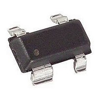
AT-41511-BLKG Avago Technologies US Inc., AT-41511-BLKG Datasheet - Page 5

AT-41511-BLKG
Manufacturer Part Number
AT-41511-BLKG
Description
TRANS NPN BIPO 12V 50MA SOT-143
Manufacturer
Avago Technologies US Inc.
Specifications of AT-41511-BLKG
Transistor Type
NPN
Voltage - Collector Emitter Breakdown (max)
12V
Noise Figure (db Typ @ F)
1dB ~ 1.7dB @ 900MHz ~ 2.4GHz
Gain
11dB ~ 15.5dB
Power - Max
225mW
Dc Current Gain (hfe) (min) @ Ic, Vce
30 @ 5mA, 5V
Current - Collector (ic) (max)
50mA
Mounting Type
Surface Mount
Package / Case
SOT-143, SOT-143B, TO-253AA
Transistor Polarity
NPN
Collector Emitter Voltage V(br)ceo
12V
Transition Frequency Typ Ft
10GHz
Power Dissipation Pd
225mW
Dc Collector Current
500mA
Dc Current Gain Hfe
270
Lead Free Status / RoHS Status
Lead free / RoHS Compliant
Frequency - Transition
-
Lead Free Status / RoHS Status
Lead free / RoHS Compliant, Lead free / RoHS Compliant
AT-41511 Typical Noise Parameters,
Common Emitter, Z
AT-41533 Typical Scattering Parameters,
AT-41511 Typical Scattering Parameters, Common Emitter, Z
AT-41533 Typical Noise Parameters,
Common Emitter, Z
Freq.
Freq.
GHz
GHz
0.1
0.5
0.9
1.0
1.5
1.8
2.0
2.4
3.0
4.0
5.0
0.1
0.5
0.9
1.0
1.5
1.8
2.0
2.4
3.0
4.0
5.0
Freq
Freq
GHz
GHz
0.1
0.9
1.8
2.4
0.1
0.9
1.8
2.4
Mag
Mag
0.49
0.53
0.53
0.53
0.54
0.55
0.56
0.57
0.60
0.64
0.67
0.34
0.19
0.20
0.20
0.24
0.25
0.27
0.29
0.33
0.39
0.45
S
S
11
11
o
F
o
F
Ang
dB
1.6
1.9
2.3
2.7
Ang
dB
-168
-168
1.3
1.6
1.9
2.1
172
169
153
145
140
129
116
161
154
132
121
115
105
min
-91
-75
= 50 Ω, V
min
93
76
60
95
79
= 50 Ω, V
29.26
18.55
13.62
12.73
29.37
17.63
12.73
11.84
-0.58
9.34
7.86
6.97
5.47
3.67
1.30
8.56
7.12
6.32
4.99
3.46
1.69
0.40
CE
CE
dB
dB
Mag
0.13
0.24
0.40
0.50
Mag
0.10
0.25
0.48
0.59
= 2.7 V, I
= 2.7 V, I
Γ Γ Γ Γ Γ
Γ Γ Γ Γ Γ
opt
opt
29.404
29.048
7.614
4.329
3.909
2.679
2.271
2.071
1.777
1.489
1.215
1.047
8.459
4.798
4.330
2.932
2.473
2.232
1.877
1.525
1.162
0.935
Mag
Mag
S
S
C
C
21
21
= 25 mA
= 25 mA
Common Emitter, Z
Ang
-162
-137
-122
Ang
-158
-122
-101
18
24
Ang
Ang
127
136
88
74
71
59
52
47
39
27
11
92
79
76
63
57
52
44
32
14
-1
-3
-37.72
-30.46
-26.56
-25.68
-22.50
-21.01
-20.09
-18.49
-16.54
-13.98
-11.90
-37.08
-25.68
-20.82
-19.91
-16.42
-14.85
-13.94
-12.32
-10.31
-7.66
-5.73
0.16
0.13
0.23
0.35
0.12
0.11
0.19
0.37
dB
dB
R
R
-
-
n
n
o
= 50 Ω, V
o
= 50 Ω, V
0.013
0.030
0.047
0.052
0.075
0.089
0.099
0.119
0.149
0.200
0.254
0.014
0.052
0.091
0.101
0.151
0.181
0.201
0.242
0.305
0.414
0.517
Mag
Mag
S
S
12
12
Figure 12. AT-41511 Gains vs.
Frequency at V
CE
Figure 13. AT-41533 Gains vs.
Frequency at V
5
= 2.7 V, I
CE
30
25
20
15
10
30
25
20
15
10
5
0
Ang
Ang
5
0
62
61
66
67
67
66
66
64
59
51
43
0
72
76
74
74
70
67
65
61
54
42
29
= 2.7 V, I
0
MSG
MSG
C
1
1
= 25 mA
S21
FREQUENCY (GHz)
S21
MAG
FREQUENCY (GHz)
CE
CE
C
Mag
Mag
0.71
0.47
0.46
0.45
0.45
0.44
0.44
0.43
0.41
0.37
0.33
0.73
0.45
0.42
0.42
0.42
0.42
0.42
0.42
0.41
0.40
0.39
= 2.7 V, I
2
= 25 mA
2
= 2.7 V, I
MAG
S
S
3
3
22
22
MSG
C
C
= 25 mA.
Ang
Ang
-106
4
= 25 mA.
-22
-23
-26
-27
-34
-38
-41
-48
-58
-75
-96
-21
-20
-24
-26
-33
-38
-41
-48
-59
-81
4
MSG
5
5


