HFA3128RZ Intersil, HFA3128RZ Datasheet - Page 3
HFA3128RZ
Manufacturer Part Number
HFA3128RZ
Description
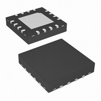
IC TRANSISTOR ARRAY PNP 16-QFN
Manufacturer
Intersil
Datasheet
1.HFA3046B.pdf
(13 pages)
Specifications of HFA3128RZ
Transistor Type
5 PNP
Voltage - Collector Emitter Breakdown (max)
15V
Frequency - Transition
5.5GHz
Noise Figure (db Typ @ F)
3.5dB @ 1GHz
Power - Max
150mW
Dc Current Gain (hfe) (min) @ Ic, Vce
20 @ 10mA, 2V
Current - Collector (ic) (max)
65mA
Mounting Type
Surface Mount
Package / Case
16-VQFN Exposed Pad, 16-HVQFN, 16-SQFN, 16-DHVQFN
Lead Free Status / RoHS Status
Lead free / RoHS Compliant
Gain
-
Available stocks
Company
Part Number
Manufacturer
Quantity
Price
Company:

Part Number:
HFA3128RZ
Manufacturer:
INTERSIL
Quantity:
201


Absolute Maximum Ratings
Collector to Emitter Voltage (Open Base) . . . . . . . . . . . . . . . . . . 8V
Collector to Base Voltage (Open Emitter) . . . . . . . . . . . . . . . . . 12V
Emitter to Base Voltage (Reverse Bias). . . . . . . . . . . . . . . . . . . 5.5V
Collector Current (100% Duty Cycle) . . . . . . 18.5mA at T
Peak Collector Current (Any Condition). . . . . . . . . . . . . . . . . . 65mA
Operating Information
Temperature Range . . . . . . . . . . . . . . . . . . . . . . . . . -55°C to 125°C
CAUTION: Stresses above those listed in “Absolute Maximum Ratings” may cause permanent damage to the device. This is a stress only rating and operation of the
device at these or any other conditions above those indicated in the operational sections of this specification is not implied.
NOTES:
Electrical Specifications
Electrical Specifications
DC NPN CHARACTERISTICS
Collector to Base Breakdown
Voltage, V
Collector to Emitter Breakdown
Voltage, V
Collector to Emitter Breakdown
Voltage, V
Emitter to Base Breakdown
Voltage, V
Collector-Cutoff-Current, I
Collector-Cutoff-Current, I
Collector to Emitter Saturation
Voltage, V
Base to Emitter Voltage, V
DC Forward-Current Transfer
Ratio, h
Early Voltage, V
Base to Emitter Voltage Drift
Collector to Collector Leakage
DYNAMIC NPN CHARACTERISTICS
Noise Figure
f
Product
1. θ
2. For θ
3. θ
T
Current Gain-Bandwidth
JA
JA
is measured with the component mounted on an evaluation PC board in free air.
is measured with the component mounted on a high effective thermal conductivity test board in free air. See Tech Brief TB379 for details.
FE
JC
(BR)CBO
(BR)CEO
(BR)CES
(BR)EBO
CE(SAT)
PARAMETER
PARAMETER
, the “case temp” location is the center of the exposed metal pad on the package underside.
A
CEO
CBO
BE
3
T
T
A
A
I
I
I
I
V
V
I
I
I
I
I
f = 1.0GHz, V
I
I
I
= 25°C
C
C
C
E
C
C
C
C
C
= 25°C
C
C
C
CE
CB
= 100µA, I
= 100µA, I
= 100µA, Base Shorted to Emitter
= 10µA, I
= 10mA, I
= 10mA
= 10mA, V
= 1mA, V
= 10mA
= 5mA, Z
= 1mA, V
= 10mA, V
HFA3046, HFA3096, HFA3127, HFA3128
= 6V, I
= 8V, I
TEST CONDITIONS
TEST CONDITIONS
34mA at T
37mA at T
B
E
C
CE
S
CE
B
E
B
= 0
= 0
CE
CE
CE
= 0
= 50Ω
= 1mA
= 0
= 0
= 3.5V
= 5V
= 2V
= 5V
= 5V,
J
J
J
= 150°C
= 125°C
= 110°C
Thermal Information
Thermal Resistance (Typical)
Maximum Power Dissipation (Any One Transistor) . . . . . . . . 0.15W
Maximum Junction Temperature (Die) . . . . . . . . . . . . . . . . . . . 175°C
Maximum Junction Temperature (Plastic Package) . . . . . . . 150°C
Maximum Storage Temperature Range . . . . . . . . . . -65°C to 150°C
Maximum Lead Temperature (Soldering 10s) . . . . . . . . . . . . 300°C
14 Ld SOIC Package (Note 1) . . . . . . .
16 Ld SOIC Package (Note 1) . . . . . . .
QFN Package (Notes 2, 3). . . . . . . . . .
(SOIC - Lead Tips Only)
MIN
MIN
5.5
12
10
40
20
8
-
-
-
-
-
-
-
-
-
TYP
0.85
TYP
-1.5
DIE
130
DIE
0.1
0.3
3.5
5.5
18
12
20
50
6
2
1
8
MAX
MAX
0.95
100
0.5
10
-
-
-
-
-
-
-
-
-
-
-
MIN
MIN
5.5
12
10
40
20
8
-
-
-
-
-
-
-
-
-
SOIC, QFN
SOIC, QFN
TYP
0.85
TYP
130
-1.5
0.1
0.3
3.5
5.5
18
12
20
50
θ
6
2
1
8
JA
120
115
(°C/W)
57
MAX
MAX
0.95
100
0.5
10
December 21, 2005
-
-
-
-
-
-
-
-
-
-
-
θ
JC
FN3076.13
UNITS
UNITS
mV/°C
N/A
N/A
(°C/W)
10
GHz
GHz
nA
nA
pA
dB
V
V
V
V
V
V
V
Related parts for HFA3128RZ
Image
Part Number
Description
Manufacturer
Datasheet
Request
R

Part Number:
Description:
Intersil Corporation [CMOS Serial Controller Interface]
Manufacturer:
Intersil Corporation
Datasheet:
Part Number:
Description:
Manufacturer:
Intersil Corporation
Datasheet:
Part Number:
Description:
357-036-542-201 CARDEDGE 36POS DL .156 BLK LOPRO
Manufacturer:
Intersil Corporation
Datasheet:
Part Number:
Description:
1024-Word x 4-Bit LSI Static RAM
Manufacturer:
Intersil Corporation
Datasheet:
Part Number:
Description:
General Purpose NPN Transistor Arrays FN341.4
Manufacturer:
Intersil Corporation
Datasheet:
Part Number:
Description:
CMOS 16-Bit Microprocessor
Manufacturer:
Intersil Corporation
Datasheet:
Part Number:
Description:
Manufacturer:
Intersil Corporation
Datasheet:
Part Number:
Description:
Manufacturer:
Intersil Corporation
Datasheet:
Part Number:
Description:
Manufacturer:
Intersil Corporation
Datasheet:
Part Number:
Description:
Manufacturer:
Intersil Corporation
Datasheet:
Part Number:
Description:
CMOS 6-Bit Latch and Decoder Memory Interfaces
Manufacturer:
Intersil Corporation
Datasheet:
Part Number:
Description:
CA3046General Purpose NPN Transistor Arrays
Manufacturer:
Intersil Corporation
Datasheet:
Part Number:
Description:
Manufacturer:
Intersil Corporation
Datasheet:
Part Number:
Description:
TR909 DLC/FLC SLIC with Low Power Standby
Manufacturer:
Intersil Corporation
Datasheet:
Part Number:
Description:
Manufacturer:
Intersil Corporation
Datasheet: