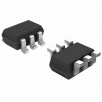
NE851M03-A CEL, NE851M03-A Datasheet - Page 9

NE851M03-A
Manufacturer Part Number
NE851M03-A
Description
TRANSISTOR NPN 2GHZ SOT-363
Manufacturer
CEL
Datasheet
1.NE851M03-T1-A.pdf
(10 pages)
Specifications of NE851M03-A
Transistor Type
NPN
Voltage - Collector Emitter Breakdown (max)
5.5V
Frequency - Transition
4.5GHz
Noise Figure (db Typ @ F)
1.9dB ~ 2.5dB @ 2GHz
Power - Max
200mW
Dc Current Gain (hfe) (min) @ Ic, Vce
100 @ 5mA, 1V
Current - Collector (ic) (max)
100mA
Mounting Type
Surface Mount
Package / Case
SC-70-6, SC-88, SOT-363
Dc Collector/base Gain Hfe Min
100
Dc Current Gain Hfe Max
145
Mounting Style
SMD/SMT
Configuration
Single
Emitter- Base Voltage Vebo
1.5 V
Continuous Collector Current
0.1 A
Power Dissipation
0.2 W
Lead Free Status / RoHS Status
Lead free / RoHS Compliant
Gain
-
Lead Free Status / RoHS Status
Lead free / RoHS Compliant, Lead free / RoHS Compliant
Life Support Applications
These NEC products are not intended for use in life support devices, appliances, or systems where the malfunction of these products can reasonably be expected to
result in personal injury. The customers of CEL using or selling these products for use in such applications do so at their own risk and agree to fully indemnify CEL for
all damages resulting from such improper use or sale.
SCHEMATIC
BJT NONLINEAR MODEL PARAMETERS
NONLINEAR MODEL
(1) Gummel-Poon Model
Parameters
RBM
MJE
CJC
VAF
CJE
VJE
VJC
VAR
IKR
ISC
IRB
IKF
ISE
NF
NE
BR
NR
NC
RE
RB
RC
IS
BF
734.5e-18
39.37e-15
27.52e-18
498.2e-15
23.22e-3
2.51e-12
759e-6
166.6
0.597
2.258
28.67
1.000
2.541
0.887
0.332
0.367
1.00
2.0
1.7
3.0
1.0
4.0
Q1
41
Parameters
XCJC
MJC
MJS
CJS
VJS
XTF
VTF
PTF
XTB
XTI
KF*
ITF
EG
AF*
FC
TR
TF
Base
L
0.6 nH
BPKG
C
0.005 pF
BEPKG
13e-12
0.122
0.668
0.75
0.39
0.06
1.11
0.1
0.5
Q1
20
0.004 nH
0
0
0
0
3
0
1
L
B
(1)
0.04 pF
C
C
0.15 pF
CBPKG
CB
Emitter
3-238
Q
1
0.004 nH
L
0.65 nH
EPKG
L
MODEL TEST CONDITIONS
Frequency:
Bias:
Date:
E
AF and KF are 1/f noise parameters and are bias dependent.
The appropriate values for the 1/f noise parameters (AF and KF)
shall be chosen from the table below, according to the desired
current range.
For a better understanding on AF and KF parameters,
please refer to AN1026.
ADDITIONAL PARAMETERS
0.28 pF
C
CE
AF
KF
L
C
0.7 nH
CPKG
0.08 pF
CEPKG
Parameters
C
C
L
L
C
C
C
L
L
L
B
E
BPKG
CPKG
EPKG
CB
CE
CBPKG
CEPKG
BEPKG
0.1 to 6.0 GHz
V
09/2003
CE
= 1.5 V, I
Collecto r
4.547e-15
I
C
= 5 mA
1.40
C
= 1 mA to 9 mA
I
855.6e-12
C
= 10 mA
A Business Partner of NEC Com p ound Semiconductor Devices, Ltd .
2.551
NE851M03
0.04 pF
0.28 pF
0.004 nH
0.004 nH
0.15 pF
0.08 pF
0.005 pF
0.6 nH
0.7 nH
0.65 nH
I
1.735e-9
C
2.626
= 15 mA
09/02/2003


