BFG 235 E6327 Infineon Technologies, BFG 235 E6327 Datasheet

TRANSISTOR RF NPN 15V SOT-223

BFG 235 E6327

Manufacturer Part Number
BFG 235 E6327
Description
TRANSISTOR RF NPN 15V SOT-223
Manufacturer
Infineon Technologies
Datasheet

Specifications of BFG 235 E6327

Transistor Type
NPN
Voltage - Collector Emitter Breakdown (max)
15V
Frequency - Transition
5.5GHz
Noise Figure (db Typ @ F)
1.7dB @ 900MHz
Gain
12.5dB
Power - Max
2W
Dc Current Gain (hfe) (min) @ Ic, Vce
75 @ 200mA, 8V
Current - Collector (ic) (max)
300mA
Mounting Type
Surface Mount
Package / Case
SOT-223 (3 leads + Tab), SC-73, TO-261
Lead Free Status / RoHS Status
Contains lead / RoHS non-compliant
Other names
BFG235E6327T
SP000010996
NPN Silicon RF Transistor*
* Short term description
ESD (Electrostatic discharge) sensitive device, observe handling precaution!
Type
BFG235
Maximum Ratings
Parameter
Collector-emitter voltage
Collector-base voltage
Emitter-base voltage
Collector current
Base current
Total power dissipation
T
Junction temperature
Ambient temperature
Storage temperature
1
2
Pb-containing package may be available upon special request
T S is measured on the collector lead at the soldering point to the pcb
S
For low-distortion broadband output amplifier
Power amplifiers for DECT and PCN systems
Integrated emitter ballast resistor
f
Pb-free (RoHS compliant) package
Qualified according AEC Q101
stages in antenna and telecommunication
systems up to 2 GHz at collector currents from
120 mA to 250 mA
T
= 5.5 GHz
80°C
Marking
BFG235 1 = E 2 = B 3 = E 4 = C -
2)
1)
Pin Configuration
1
Symbol
V
V
V
V
I
I
P
T
T
T
C
B
CEO
CES
CBO
EBO
tot
j
A
stg
4
-65 ... 150
-65 ... 150
-
Value
300
150
15
25
25
40
2
2
Package
SOT223
2007-04-20
BFG235
Unit
V
mA
W
°C
1
2
3

Related parts for BFG 235 E6327

BFG 235 E6327 Summary of contents

Page 1

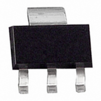
NPN Silicon RF Transistor* For low-distortion broadband output amplifier stages in antenna and telecommunication systems GHz at collector currents from 120 mA to 250 mA Power amplifiers for DECT and PCN systems Integrated emitter ballast resistor f ...

Page 2

Thermal Resistance Parameter 1) Junction - soldering point Electrical Characteristics at T Parameter DC Characteristics Collector-emitter breakdown voltage mA Collector-emitter cutoff current Collector-base ...

Page 3

Electrical Characteristics at T Parameter AC Characteristics (verified by random sampling) Transition frequency I = 200 mA 200 MHz C CE Collector-base capacitance MHz ...

Page 4

Total power dissipation P tot 2200 mW 1800 1600 1400 1200 1000 800 600 400 200 Permissible Pulse Load totmax totDC 0.005 ...

Page 5

Package Outline A 0.7 Foot Print Marking Layout (Example) Packing Reel ø180 mm = 1.000 Pieces/Reel Reel ø330 mm = 4.000 Pieces/Reel Pin 1 Package SOT223 6.5 ±0.2 3 ±0 2.3 ±0.1 4.6 0. ...

Page 6

... For information on the types in question please contact your nearest Infineon Technologies Office. Infineon Technologies Components may only be used in life-support devices or systems with the express written approval of Infineon Technologies failure of such components can reasonably be expected to cause the failure of that life-support device or system affect the safety or effectiveness of that device or system ...

Related keywords