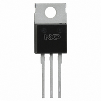
BT151-500RT,127 NXP Semiconductors, BT151-500RT,127 Datasheet

BT151-500RT,127
Specifications of BT151-500RT,127
Related parts for BT151-500RT,127
BT151-500RT,127 Summary of contents
Page 1
... BT151-500RT SCR mA, 500 V, SOT78 Rev. 01 — 18 May 2009 1. Product profile 1.1 General description Planar passivated SCR (Silicon Controlled Rectifier SOT78 plastic package 1.2 Features and benefits High reliability High surge capability 1.3 Applications Ignition circuits Motor control 1.4 Quick reference data Table 1 ...
Page 2
... BT151-500RT TO-220AB; plastic single-ended package; heatsink mounted; 1 mounting hole; 3-lead SC-46 TO-220AB BT151-500RT_1 Product data sheet SCR mA, 500 V, SOT78 Simplified outline SOT78 (TO-220AB; SC-46) Rev. 01 — 18 May 2009 BT151-500RT Graphic symbol sym037 Version SOT78 © NXP B.V. 2009. All rights reserved ...
Page 3
... Figure 4; see Figure ms; sin-wave pulse p over any 20 ms period 003aad205 16 I T(RMS) ( surge duration (s) Fig 2. RMS on-state current as a function of mounting base temperature; maximum values Rev. 01 — 18 May 2009 BT151-500RT SCR mA, 500 V, SOT78 Min Max - 500 - 500 - -40 150 - 150 - 132 ...
Page 4
... TSM (A) 120 Fig 4. Non-repetitive peak on-state current as a function of the number of sinusoidal current cycles; maximum values BT151-500RT_1 Product data sheet 2.8 4 Rev. 01 — 18 May 2009 BT151-500RT SCR mA, 500 V, SOT78 003aad202 a = 1.57 1.9 2.2 conduction form angle factor (degrees 2.8 90 2.2 120 1 ...
Page 5
... Z th(j-mb) (K/ Fig 6. Transient thermal impedance from junction to mounting base as a function of pulse width BT151-500RT_1 Product data sheet 4 10 Conditions see Figure Rev. 01 — 18 May 2009 BT151-500RT SCR mA, 500 V, SOT78 003aad204 TSM max j(init (s) p Min Typ Max - - 1 001aaa962 t p ...
Page 6
... 125 ° 500 125 ° 500 125 ° 001aaa949 GT( 100 150 Fig 8. Normalized gate trigger current as a function of junction temperature Rev. 01 — 18 May 2009 BT151-500RT SCR mA, 500 V, SOT78 Min Typ Max 50 130 - 200 1000 - - 1.4 1.75 - 0.6 1.5 0.25 0.4 ...
Page 7
... GT(25 C) 1.2 (2) (3) 0.8 0.4 1 (V) T Fig 12. Normalized gate trigger voltage as a function of junction temperature Rev. 01 — 18 May 2009 BT151-500RT SCR mA, 500 V, SOT78 003aab826 0 50 100 150 003aab823 0 50 100 150 © NXP B.V. 2009. All rights reserved ...
Page 8
... 0.7 16.0 6.6 10.3 15.0 2.54 0.4 15.2 5.9 9.7 12.8 REFERENCES JEDEC JEITA SC-46 3-lead TO-220AB Rev. 01 — 18 May 2009 BT151-500RT SCR mA, 500 V, SOT78 mounting base Q c ( max. 3.30 3.8 3.0 2.6 3.0 2.79 3.5 2.7 2.2 ...
Page 9
... NXP Semiconductors 8. Revision history Table 7. Revision history Document ID Release date BT151-500RT_1 20090518 BT151-500RT_1 Product data sheet Data sheet status Change notice Product data sheet - Rev. 01 — 18 May 2009 BT151-500RT SCR mA, 500 V, SOT78 Supersedes - © NXP B.V. 2009. All rights reserved ...
Page 10
... Export might require a prior authorization from national authorities. 9.4 Trademarks Notice: All referenced brands, product names, service names and trademarks are the property of their respective owners. http://www.nxp.com salesaddresses@nxp.com Rev. 01 — 18 May 2009 BT151-500RT SCR mA, 500 V, SOT78 © NXP B.V. 2009. All rights reserved ...
Page 11
... Please be aware that important notices concerning this document and the product(s) described herein, have been included in section ‘Legal information’. © NXP B.V. 2009. For more information, please visit: http://www.nxp.com For sales office addresses, please send an email to: salesaddresses@nxp.com Document identifier: BT151-500RT_1 All rights reserved. Date of release: 18 May 2009 ...


