PMB8818TP Ericsson Power Modules, PMB8818TP Datasheet - Page 29
PMB8818TP
Manufacturer Part Number
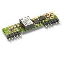
PMB8818TP
Description
DC/DC Power Supply Single-OUT 0.75V to 5.5V 16A 80W 10-Pin
Manufacturer
Ericsson Power Modules
Type
Step Downr
Series
PMBr
Datasheet
1.PMB8818TP.pdf
(32 pages)
Specifications of PMB8818TP
Output Current
16 A
Output Voltage
0.75 to 5.5 V
Input Voltage
12 V
Number Of Outputs
1
Output Power
80 W
Input Voltage Range
8.3 V to 16 V
Output Voltage (channel 1)
0.75 V to 5.5 V
Output Current (channel 1)
16 A
Package / Case Size
SIP
Output Type
Non-Isolated
Lead Free Status / Rohs Status
Lead free / RoHS Compliant


Remote Sense
All PMB 8000 Series DC/DC regulators have a positive re-
mote sense pin that can be used to compensate for moder-
ate amounts of resistance in the distribution system and al-
low for voltage regulation at the load or other selected point.
The remote sense line will carry very little current and does
not need a large cross sectional area. However, the sense
line on the PCB should be located close to a ground trace or
ground plane. The remote sense circuitry will compensate for
up to 10% voltage drop between the sense voltage and the
voltage at the output pins from V
not needed the sense pin should be left open or connected
to the positive output.
Operating Information
Current Limit Protection
The PMB 8000 Series DC/DC regulators include current
limiting circuitry that allows them to withstand continuous
overloads or short circuit conditions on the output. The out-
put voltage will decrease towards zero for output currents in
excess of max output current (Iomax). When the current limit
is reached the regulator will go into hiccup mode. The cur-
rent limit is temperature dependent, i.e. the limit decrease
at higher operating temperature, the regulator is guaranteed
to start at I
resume normal operation after removal of the overload. The
load distribution system should be designed to carry the
maximum output short circuit current specified.
Over Temperature Protection (OTP)
The PMB 8000 Series DC/DC regulators are protected from
thermal overload by an internal over temperature shutdown
circuit. When the PCB temperature near the IC circuit reach-
es 130 °C the converter will shut down immediately. The
regulator will make continuous attempts to start up (non-
latching mode) and resume normal operation automatically
when the temperature has dropped below the temperature
threshold.
Input And Output Impedance
The impedance of both the power source and the load will
interact with the impedance of the DC/DC regulator. It is
most important to have a low characteristic impedance,
both at the input and output, as the regulators have a low
energy storage capability. Use capacitors across the input if
the source inductance is greater than 4.7 mH. Suitable input
capacitors are 22 mF - 220 mF low ESR ceramics.
Minimum Required External Capacitors
Required Input Filter
External input capacitors are required to increase the life-
time of the internal capacitors. Low ESR ceramics should be
used, the minimum input capacitance is stated below:
PMB 8818T P 2 x 4.7 mF
PMB 8818T P Datasheet
O
max x 1.25 @ Tref 115°C. The regulator will
O
nom. If the remote sense is
Note: All output characteristics in the datasheet are measured with 4 x 4.7 µF at the input pins.
Optional Input Filter
To minimize input ripple and to ensure even better stability
more capacitors can be added, see table below.
Consider the max output power in a given application and
choose sufficient capacitors to obtain desired ripple level.
Make sure that the extra capacitors are placed near the input
pins. The table below is just an example since the board
layout also has effect on the result.
Required output filter
External output capacitance is also required to reduce the
output ripple and to obtain specified load step response. It
is recommended to use low ESR polymer capacitors or low
ESR ceramic capacitors.
Minimum requirement:
PMB 8818T P
This is the output filter used in the verification and needed to
meet the specification.
Maximum Capacitive Load
When powering loads with significant dynamic current
requirements, the voltage regulation at the load can be
improved by addition of decoupling capacitance at the load.
The most effective technique is to locate low ESR ceramic
capacitors as close to the load as possible, using several
capacitors to lower the total ESR. These ceramic capacitors
will handle short duration high-frequency components
of dynamic load changes. In addition, higher values of
capacitors (electrolytic capacitors) should be used to handle
the mid-frequency components. It is equally important
to use good design practice when configuring the DC
distribution system.
Low resistance and low inductance PCB layouts and
cabling should be used. Remember that when using remote
sensing, all resistance (including the ESR), inductance and
capacitance of the distribution system is within the feedback
loop of the regulator. This can affect on the regulators
compensation and the resulting stability and dynamic
response performance.
Very low ESR and high capacitance must be used with
care. A “rule of thumb” is that the total capacitance must
never exceed typically 500-700 mF if only low ESR (< 2mΩ)
ceramic capacitors are used. If more capacitance is needed,
a combination of low ESR type and electrolytic capacitors
should be used, otherwise the stability will be affected.
Output power
20-40 W
40-60 W
60-80 W
0-20 W
11 x 4.7 µF
2 x 150 µF. (low ESR polymer type).
2 x 4.7 µF
5 x 4.7 µF
8 x 4.7 µF
EN/LZT 146 066 R2A © Ericsson Power Modules, April 2007
150
Desired input ripple (mV
2 x 4.7 µF
4 x 4.7 µF
7 x 4.7 µF
-----
250
p-p
)
2 x 4.7 µF
4 x 4.7 µF
-----
-----
500
Related parts for PMB8818TP
Image
Part Number
Description
Manufacturer
Datasheet
Request
R

Part Number:
Description:
37.5-150W DC/DC POWER MODULES
Manufacturer:
Ericsson Power Modules
Part Number:
Description:
DC/DC Power Supply Dual-OUT 3.3V/5V 9.6A/6.4A 40W 10-Pin
Manufacturer:
Ericsson Power Modules
Part Number:
Description:
DC/DC Power Supply Single-OUT 3.3V 20A 66W 8-Pin Quarter-Brick
Manufacturer:
Ericsson Power Modules
Datasheet:
Part Number:
Description:
DC/DC Power Supply Single-OUT 1.8V 50A 90W 11-Pin
Manufacturer:
Ericsson Power Modules
Part Number:
Description:
Module DC-DC 1-OUT 1.8V 30A 54W 9-Pin
Manufacturer:
Ericsson Power Modules

Part Number:
Description:
Module DC-DC 1-OUT 1.8V 60A 108W 11-Pin Half-Brick
Manufacturer:
Ericsson Power Modules
Datasheet:

Part Number:
Description:
Module DC-DC 1-OUT 12V 25A 300W 11-Pin Half-Brick
Manufacturer:
Ericsson Power Modules
Part Number:
Description:
Module DC-DC 1-OUT 5V 20A 100W Quarter-Brick
Manufacturer:
Ericsson Power Modules

Part Number:
Description:
Module DC-DC 1-OUT 12V 6A 72W 8-Pin 1/8-Brick
Manufacturer:
Ericsson Power Modules
Datasheet:
Part Number:
Description:
Module DC-DC 1-OUT 5.05V 2A 10W 18-Pin SMD
Manufacturer:
Ericsson Power Modules
Part Number:
Description:
Manufacturer:
Ericsson Power Modules
Datasheet:

Part Number:
Description:
Module DC-DC 1-OUT 5V 60A 300W 11-Pin Half-Brick Tray
Manufacturer:
Ericsson Power Modules
Part Number:
Description:
Module DC-DC 1-OUT 12V 1A 12W 18-Pin
Manufacturer:
Ericsson Power Modules
Datasheet:
Part Number:
Description:
Module DC-DC 2-OUT 12V/-12V 0.25A 6W 18-Pin SMD
Manufacturer:
Ericsson Power Modules
Part Number:
Description:
Module DC-DC 1-OUT 28V 11A 310W 11-Pin Half-Brick Tray
Manufacturer:
Ericsson Power Modules
Datasheet: